Low dose CT denoising

A technology of noise reduction and denoiser, applied in image enhancement, image analysis, 2D image generation, etc., can solve the problems of high reconstruction calculation cost and hindering application, etc.

Active Publication Date: 2013-06-26
KONINKLIJKE PHILIPS ELECTRONICS NV
View PDF4 Cites 5 Cited by
  • Summary
  • Abstract
  • Description
  • Claims
  • Application Information

AI Technical Summary

Problems solved by technology

However, ML-based reconstruction is extremely computationally expensive, which currently hinders its application in routine practice

Method used


Image

  • Low dose CT denoising
  • Low dose CT denoising
  • Low dose CT denoising

Examples


Embodiment Construction

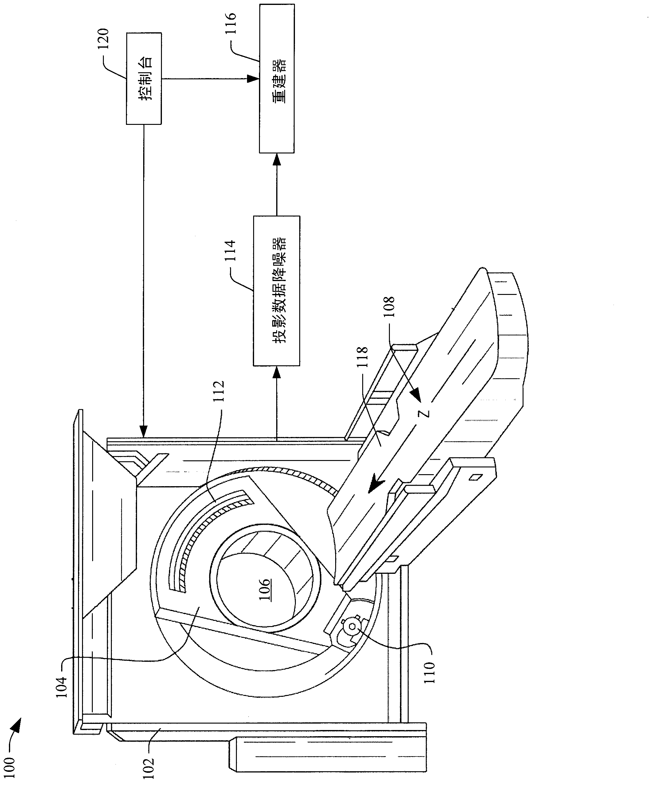
[0013] figure 1 An imaging system 100 is shown, which may be, for example, a computed tomography (CT) scanner. Imaging system 100 includes a substantially stationary gantry 102 and a rotating gantry 104 . A rotating gantry 104 is rotatably supported by the stationary gantry 102 and rotates about an examination region 106 about a longitudinal or z-axis 108 .

[0014] A radiation source 110 such as an X-ray tube is rotatably supported by a rotating gantry 104 . Radiation source 110 rotates with rotating gantry 104 and emits radiation that traverses examination region 106 . The source collimator includes collimating members that collimate radiation so that it forms a radiation beam that is generally cone-shaped, wedge-shaped, fan-shaped, or otherwise shaped.

[0015] The two-dimensional radiation-sensitive detector array 112 defines an angled arc opposite the radiation source 110 across the examination region 106 . The detector array 112 includes a plurality of rows of detect...


PUM


Abstract

A system includes a source that rotates about an examination region and emits radiation that traverses the examination region, a radiation sensitive detector array that detects radiation traversing the examination region and generates projection data indicative of the detected radiation, and a projection data de-noiser that de-noises the projection data, wherein the de-noiser de-noises a projection based on a number of detected photons for the projection.

Description

technical field [0001] The following generally relates to noise reduction of data, which is particularly applicable to computed tomography (CT), but is equally applicable to other imaging modalities, for example, hybrid PET / CT systems, digital X-ray systems, and / or other imaging modalities . Background technique [0002] A multi-slice computed tomography (CT) scanner includes an x-ray tube mounted on a rotatable gantry that rotates about a longitudinal or z-axis around an examination region. The X-ray tube emits radiation across the examination region and the subject or object within it. The two-dimensional detector array defines an angled arc opposite the X-ray tube across the examination region. The detector array includes a plurality of rows of detectors aligned relative to each other and extending along the z-axis. The detectors detect radiation traversing the examination region and a subject or object within it and generate projection data indicative thereof. A reco...

Claims


Application Information

Patent Timeline
Patent Type & Authority Applications(China)
IPC IPC(8): G06T5/00G06T11/00
CPCG06T5/002G06T11/005G06T2207/10081G06T2207/20004G06T5/001
Inventor K·M·布朗S·扎比奇
Owner KONINKLIJKE PHILIPS ELECTRONICS NV
Why Eureka
Try Eureka