Turning-milling linkage machining method of large-pitch worm

A processing method and large pitch technology, applied in the direction of worms, toothed components, belts/chains/gears, etc., can solve the problems of low efficiency, long processing cycle, high manufacturing cost, etc., and achieve improved processing efficiency and accurate processing pitch , The effect of shortening the processing time

Inactive Publication Date: 2013-07-03
BEIJING TECHNOLOGY AND BUSINESS UNIVERSITY
View PDF4 Cites 10 Cited by
  • Summary
  • Abstract
  • Description
  • Claims
  • Application Information

AI Technical Summary

Problems solved by technology

If it is used to process large-pitch screws, it will result in long processing cycle, low efficiency and high manufacturing cost

Method used


Image

  • Turning-milling linkage machining method of large-pitch worm
  • Turning-milling linkage machining method of large-pitch worm
  • Turning-milling linkage machining method of large-pitch worm

Examples


Embodiment 1

[0026] The workpiece to be processed is: the modulus is 20mm; the number of worm heads is 1; the normal pressure angle is 20; the helix angle is 5°30';

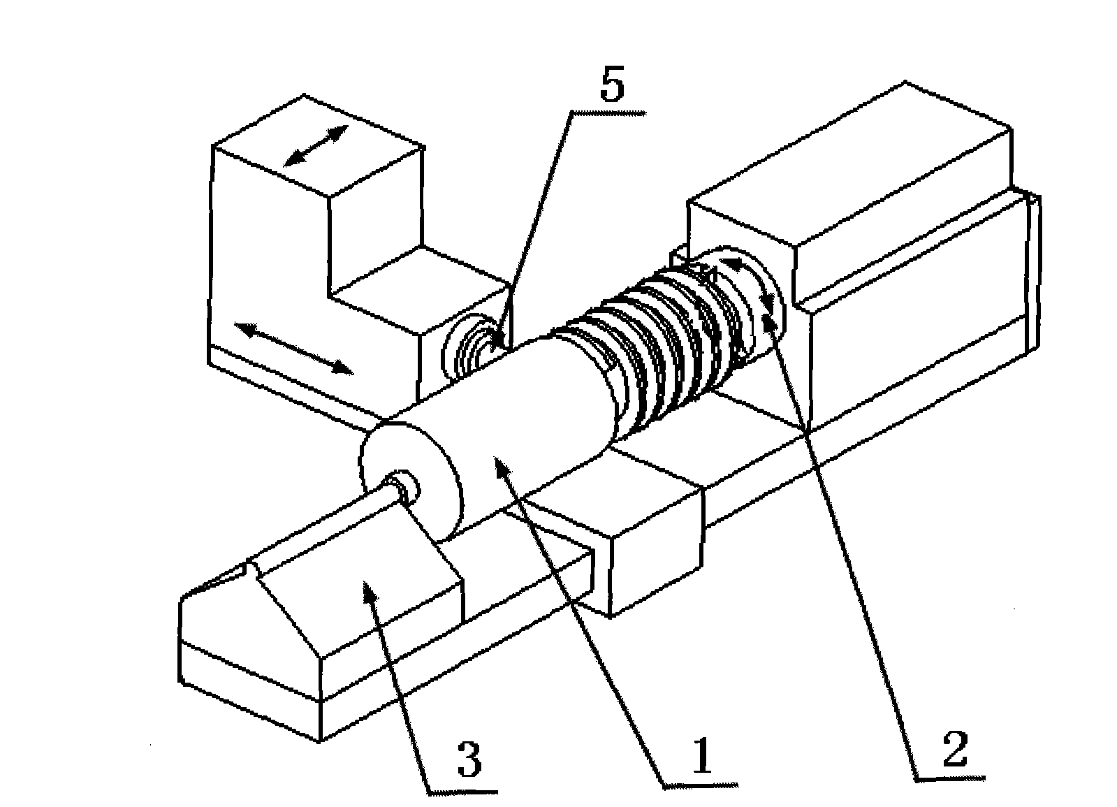
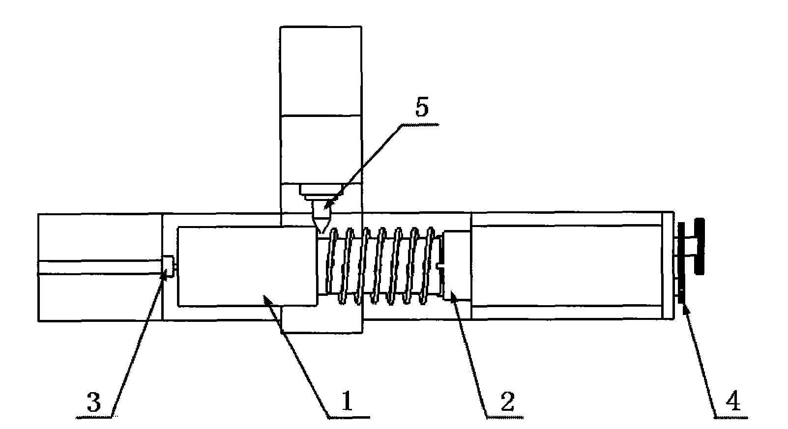
[0027] On the shovel lathe, the worm part 1 to be processed is fixed on the workpiece spindle of the shovel lathe through the three-jaw chuck 2 and the bed end tip 3. The shovel lathe replaces the hanging wheel according to the pitch of the worm to be processed, and adopts a vertical axis that is perpendicular to the part to be processed. The finger-shaped milling cutter 5 installed on the main axis mills the surface of the shaft worm part to be machined through axial and tangential feeds, and the to-be-machined part fixed on the lathe only rotates axially along the main shaft, and the rotational speed of the main shaft of the lathe is 0.2 r / min, the cutting speed of the finger milling cutter is 60r / min, the axial feed is 2mm / min, and the depth of cut is 15mm. noodle.

[0028] The main parameters of the milling cutter: the m...

Embodiment 2

[0031] A turning-milling linkage machining method of a large-pitch worm

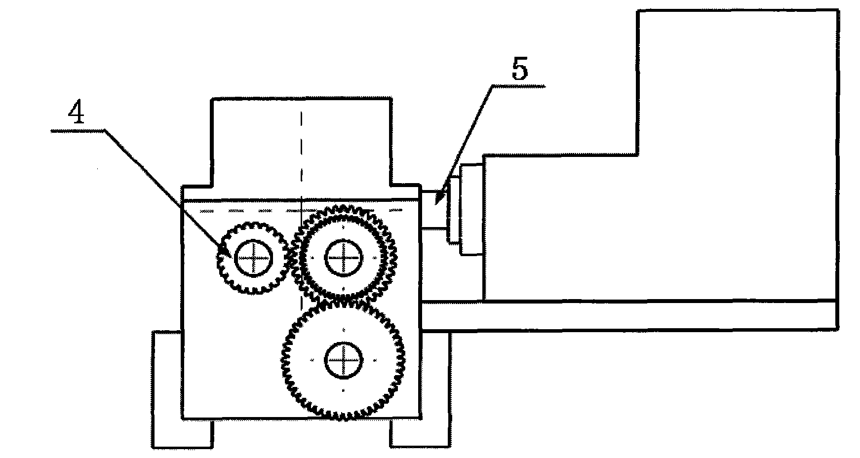
[0032] For shaft worm parts, on the shovel lathe, fix the worm part 1 to be processed on the workpiece spindle of the shovel lathe through the three-jaw chuck 2 and the bed end tip 3, and replace the shovel lathe's hanging wheel 4 to get the appropriate hanger. The wheel ratio meets the requirements of the thread pitch of the worm to be processed, and a finger-shaped milling cutter 5 installed perpendicular to the main axis of the part to be processed is used to mill the surface of the shaft worm part to be processed through axial and tangential feed, and is fixed on the lathe. The parts to be machined only rotate axially along the spindle, the spindle speed of the lathe is 0.2r / min, the speed of the finger milling cutter is 60r / min, the axial feed is 1-12mm / min, and the depth of cut is 15mm. Turning and milling are linked together, and pressure coolant is used to flush the surface of the machined parts ...


PUM


Abstract

The invention discloses a turning-milling linkage machining method of a large-pitch worm, and relates to the technical field of worm machining methods. The method comprises the following steps of: on a formrelieved tooth lathe, fixing parts to be machined onto the lathe through a three-paw chuck and a centre, wherein the rotation speed of a main shaft of the lathe is 0.1-10r / min, milling the surfaces of the parts by a finger-shaped milling cutter, wherein the rotation speed is 30-80r / min when the finger-shaped milling cutter is used for cutting, the axial feed quantity is 1-12mm / min, the cutting depth is 15mm, the modules of the milling cutter are those of the parts to be machined, the other parameters of teeth of the milling cutter are accordant with the parameters of the worm to be machined, and the installing position of the milling cutter is perpendicular to the principal axis of the parts to be machined, changing a change gear according to the worm machining pitch by the formrelieved tooth lathe to adjust the change gear ratio, and washing the surfaces of the parts to be machined by pressure cooling liquid to form the tooth surface of the worm. The machining method can be used for machining the large-pitch worm, and is high in machining efficiency, and accurate in pitch, and the stepless adjustment on the pitch within a certain range can be realized.

Description

technical field [0001] The invention relates to the technical field of worm processing methods, in particular to a processing method of a large-pitch worm. Background technique [0002] A worm is a transmission mechanism that meshes with a worm gear or a helical gear and is used to transmit motion or force. It is often used to transmit motion and force between two staggered shafts. At present, there are three main worm processing methods: turning, milling, and cutting. [0003] 1. Turning [0004] Turning worms is the most common basic method for machining worms. The worm turning tool is simple in structure, easy to manufacture, and has strong versatility, and can be turned on various lathes. The turning worm has a wide range of processing and is not limited by the diameter, but the efficiency of turning worm is relatively low, and it is mainly used in single-piece and small batch production. Moreover, the processing quality mainly depends on the technical level of worke...

Claims


Application Information

Patent Timeline
Patent Type & Authority Applications(China)
IPC IPC(8): B23F13/02
Inventor 石文天刘玉德石凤德
Owner BEIJING TECHNOLOGY AND BUSINESS UNIVERSITY
Why Eureka
Try Eureka