
Combination machining method of front half body of riding type motorcycle frame and auxiliary device thereof

A riding motorcycle and combined processing technology, which is applied in the direction of auxiliary equipment, motorcycles, auxiliary welding equipment, etc., can solve the installation position error of the engine installation hole position and shock absorber, affect the installation quality, and the installation accuracy of the engine and shock absorber Reduce and other problems, achieve the effect of improving installation quality, ensuring installation accuracy, and improving installation accuracy

Inactive Publication Date: 2013-07-03
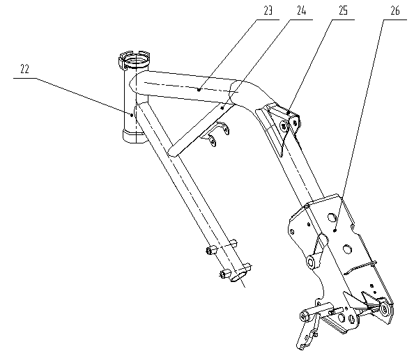
力帆科技(集团)股份有限公司
View PDF6 Cites 32 Cited by
  • Summary
  • Abstract
  • Description
  • Claims
  • Application Information

AI Technical Summary

Problems solved by technology

This existing processing method easily leads to errors in the engine mounting hole position and the shock absorber installation position, which in turn leads to a decrease in the installation accuracy of the engine and shock absorber, which affects the installation quality

Method used


Image

  • Combination machining method of front half body of riding type motorcycle frame and auxiliary device thereof
  • Combination machining method of front half body of riding type motorcycle frame and auxiliary device thereof
  • Combination machining method of front half body of riding type motorcycle frame and auxiliary device thereof

Examples


Embodiment Construction

[0030] The present invention will be further described in detail below in conjunction with the accompanying drawings and specific embodiments.

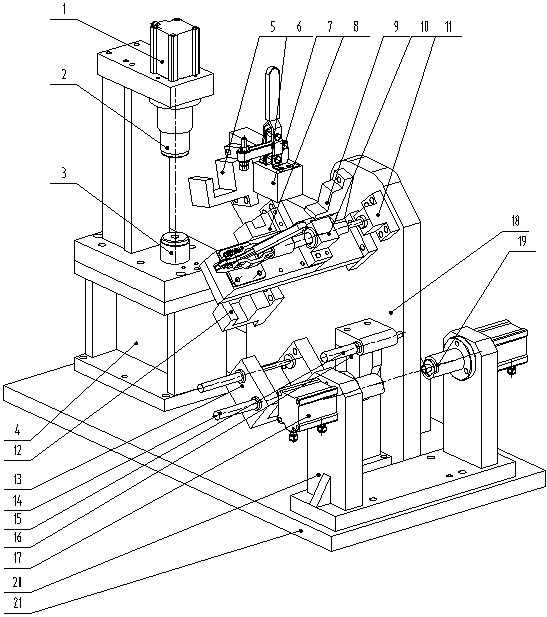
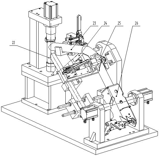
[0031] Such as Figure 2-3 As shown, the auxiliary device disclosed in this specific embodiment is a combined processing auxiliary device for the front half of the motorcycle frame, including a base plate 21, a combined positioning mechanism for the head tube assembly and a main positioning mechanism arranged on the base plate 21. , connecting pipe positioning mechanism, shock absorbing box positioning mechanism and engine main suspension combined positioning mechanism; the head tube assembly combined positioning mechanism, supervisory positioning mechanism, connecting pipe positioning mechanism, shock absorbing box positioning mechanism and engine main suspension combined positioning mechanism Used to realize the fixing of the head tube assembly 22, the main pipe 23, the connecting pipe 24, the shock absorber 25 and the engine main s...


PUM


Abstract

The invention discloses a combination machining method of the front half body of a riding type motorcycle frame and an auxiliary device of the front half body of the riding type motorcycle frame. The device comprises a base plate as well as a motorcycle head pipe assembly combination positioning mechanism, a main pipe positioning mechanism, a connecting pipe positioning mechanism, a shock absorption box positioning mechanism and an engine master suspension combination positioning mechanism arranged on the base plate; and a positioning point in the positioning mechanism comprises two engine liner pipes arranged on a front slantwise pipe, a positioning point of the shock absorption box positioning mechanism is a shock absorption shaft hole, and a positioning point of the engine master suspension combination positioning mechanism is a bottom fork shaft sleeve hole and an engine installing hole in an engine master suspension. In the method, each component of the front half body combination of the motorcycle frame is clamped by the auxiliary device and completely welded after being interpedently machined, and then other members of the frame can be welded. The method and the auxiliary device have the advantages of being simple in device structure, low in cost, reliable to position and convenient to operate, so that the engine installing precision can be guaranteed, and the riding type motorcycle frame engine installing quality can be improved.

Description

technical field [0001] The invention relates to the field of processing a riding motorcycle frame, in particular to a combined processing method for the front half of a riding motorcycle frame and an auxiliary device thereof. [0002] Background technique [0003] Among the motorcycles, riding motorcycles, as a classic model, have the advantages of high power and good long-distance driving performance, and are deeply loved by consumers. [0004] In a new riding motorcycle model 150-10B, the structure of the front half of the frame is as follows: figure 1 As shown, it includes a head tube assembly combination 22, a main pipe 23, a connecting pipe 24, a shock absorber box 25 and an engine main suspension combination 26 composed of a head tube (also known as a riser) and a front inclined tube. Wherein, the front end of the front inclined pipe is connected to the head pipe, and the rear end extends downwards and runs through two engine liners for installing the engine. The fro...

Claims


Application Information

Patent Timeline
IPC IPC(8): B23K37/04B62K11/02
Inventor 陈勇江李孙仁兵罗书平
Owner 力帆科技(集团)股份有限公司
Learn More