Method for molding and producing resonance rod by adopting flow control

A technology of flow control and resonance rod, applied in the field of manufacturing resonance rod by flow control molding, can solve the problems that cannot be widely used, restrict the development of the communication industry, and hinder the production of resonance rod, so as to improve the operability, simplify the structure, The effect of improving mechanical properties

Inactive Publication Date: 2013-07-03
危宾
View PDF7 Cites 8 Cited by
  • Summary
  • Abstract
  • Description
  • Claims
  • Application Information

AI Technical Summary

Problems solved by technology

Due to the stretching characteristics of the stretched resonant rod, the R angle of the material bending leads to a low electrical index of the system, while the multi-station cold heading machine is a device for producing large quantities of standard parts such as screws, due to its high efficiency , so there is a requirement for the minimum production volume of parts, because the size of the resonant rod is adjusted at any time with the working environment, so it cannot be widely used at present
The above reasons have caused obstacles to the production of resonant rods, which seriously restricted the development of the communication industry.

Method used


Image

  • Method for molding and producing resonance rod by adopting flow control
  • Method for molding and producing resonance rod by adopting flow control
  • Method for molding and producing resonance rod by adopting flow control

Examples


Embodiment Construction

[0035] The technical solutions of the present invention will be clearly and completely described below in conjunction with the accompanying drawings of the present invention. Obviously, the described embodiments are only some of the embodiments of the present invention, not all of them. Based on the embodiments of the present invention, all other embodiments obtained by persons of ordinary skill in the art without creative efforts fall within the protection scope of the present invention.

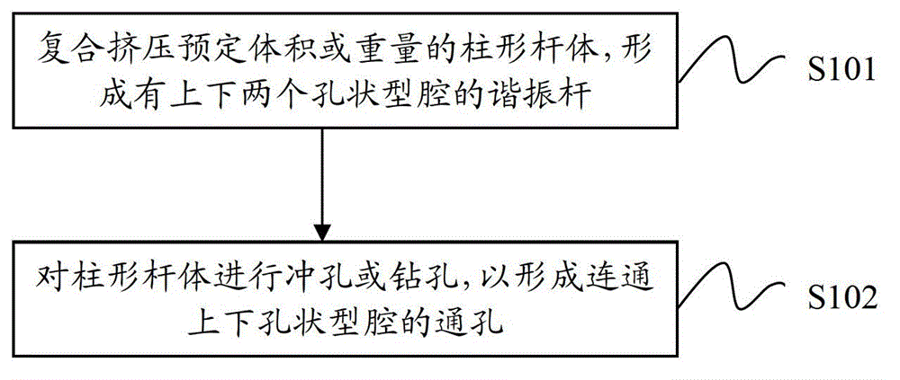
[0036] Such as figure 1 As shown, the present invention provides a method for manufacturing a resonant rod by flow control molding. The resonant rod includes a rod body and hole-shaped cavities located at both ends of the rod body. The method includes the following steps:

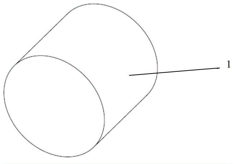
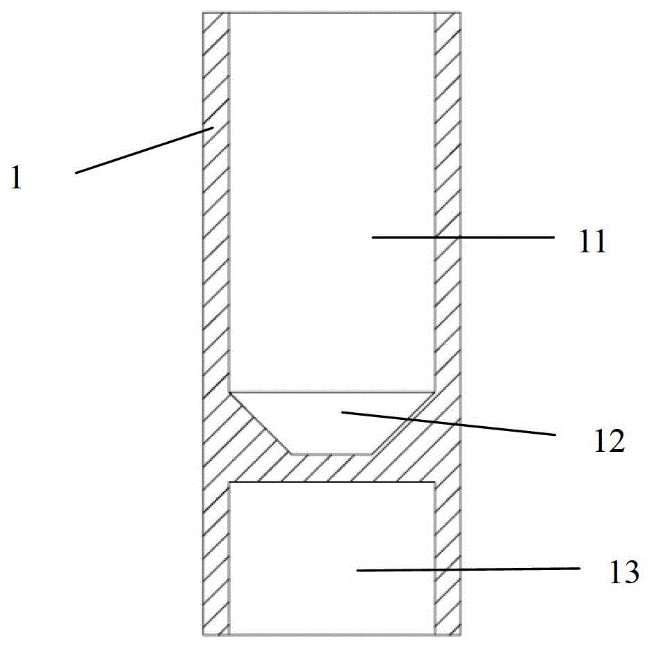
[0037] Step S101, composite extruding a cylindrical rod with a predetermined volume or weight, such as figure 2 As shown, the cylindrical rod body 1 used in this embodiment is a low carbon steel cylinder with a diamete...


PUM

PropertyMeasurementUnit
lengthaaaaaaaaaa
diameteraaaaaaaaaa
diameteraaaaaaaaaa

Abstract

The invention provides a method for molding and producing a resonance rod by adopting flow control. The resonance rod comprises a rod body and hole-shaped cavities positioned at the two ends of the rod body. The method comprises the following steps: extruding a column-shaped rod body with predetermined weight or size in a combined manner; forming a first column hole and an annular cone hole both axially arranged inside one side of the column-shaped rod body and forming a second column hole axially arranged inside the other side of the column-shaped rod body, wherein the first column hole and the second column hole are positioned at the two ends of the rod body; and punching or drilling the column-shaped rod body to form a through hole for communicating the annular cone hole with the second column hole. According to the method, no cuttings are produced during the production process of combined extrusion; material and labor cost is saved; the minimum order quantity of products is not required; the much debug time of dies is saved; and besides, the combined extrusion can realize once formation at one position, thus, the machining efficiency is higher; and nonferrous metals such as copper and aluminum, and ferrous metal raw materials made of mild carbon steel of various grades can be machined.

Description

technical field [0001] The invention relates to a manufacturing process of a resonant rod, in particular to a method for manufacturing a resonant rod by flow control forming. Background technique [0002] The world has entered the information age, and mobile communication plays a pivotal role in information transmission. With the rapid development of communication technology, radio frequency technology plays an irreplaceable role. The resonant rod is an indispensable part in radio frequency technology, and the annual usage in the world is tens of millions. With the substantial improvement of my country's equipment manufacturing level, the world's well-known communication equipment manufacturing companies are purchasing or manufacturing related parts in China. [0003] The dimensional accuracy of the resonant rod is very high and the structure is complex. The traditional manufacturing process is generally lathe manufacturing. This method is not only inefficient but also con...

Claims


Application Information

Patent Timeline
Patent Type & Authority Applications(China)
IPC IPC(8): B23P15/00B21C23/08
Inventor 危宾杨艳玲
Owner 危宾
Why Eureka
Try Eureka