Plastic composite body and manufacturing method thereof

A manufacturing method and composite technology, which are applied in chemical instruments and methods, thin material processing, synthetic resin layered products, etc., can solve the problems of broken inserts, large scour force, and increased internal stress of plastic composites, and reduce the Internal stress, the effect of reducing the scour force

Inactive Publication Date: 2013-07-03
SHENZHEN FUTAIHONG PRECISION IND CO LTD
View PDF6 Cites 7 Cited by
  • Summary
  • Abstract
  • Description
  • Claims
  • Application Information

AI Technical Summary

Problems solved by technology

However, in the above-mentioned high temperature and high pressure injection molding process, the large scouring force generated is easy to damage the insert and increase the internal stress of the plastic composite.

Method used


Image

  • Plastic composite body and manufacturing method thereof
  • Plastic composite body and manufacturing method thereof
  • Plastic composite body and manufacturing method thereof

Examples


Embodiment Construction

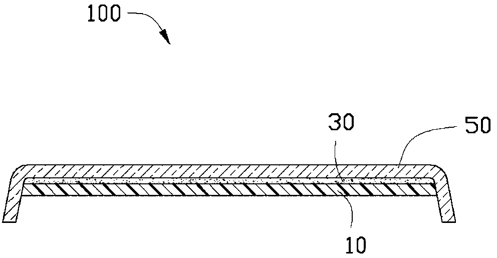
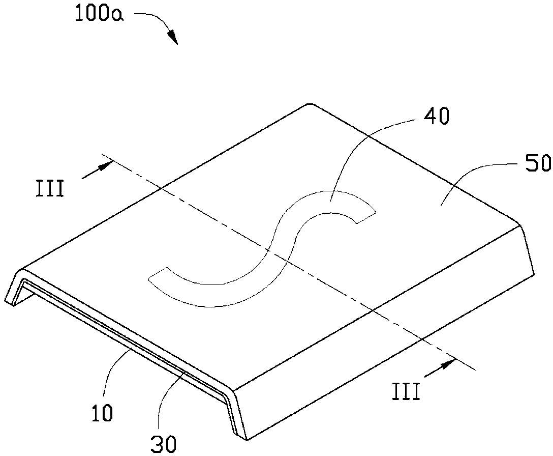
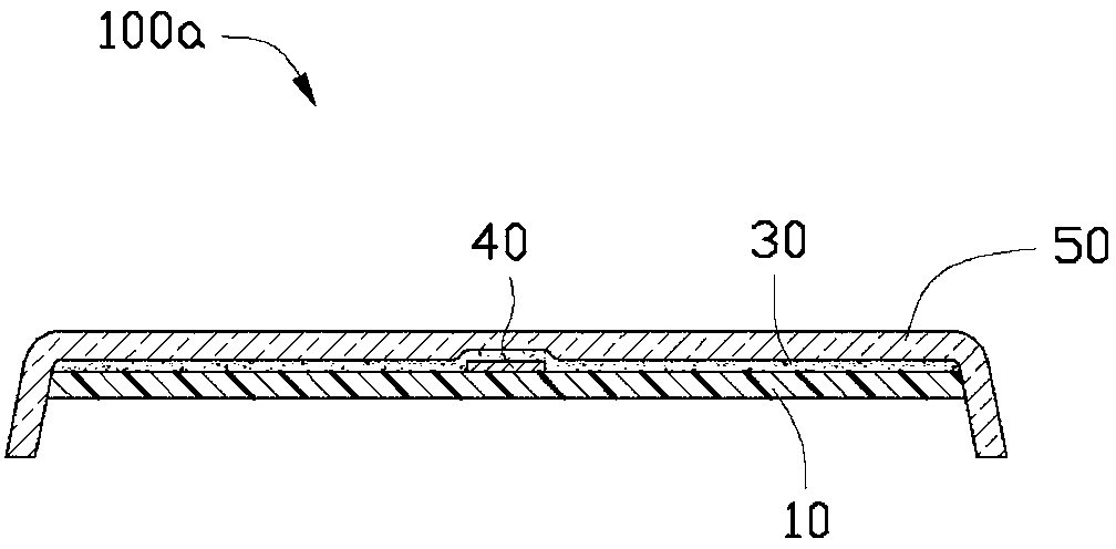
[0022] see figure 1 , The plastic composite 100 of a preferred embodiment of the present invention includes a first plastic part 10 , an adhesive layer 30 and a second plastic part 50 sequentially formed on the first plastic part 10 .

[0023] The material of the first plastic part 10 can be polycarbonate (PC), polymethyl methacrylate (PMMA), a blend of polycarbonate (PC) and polyethylene terephthalate (PET) Any of thermoplastic resins such as polyamide (PA), acrylonitrile-styrene-butadiene copolymer resin (ABS) and polyurethane (PU). Preferably, glass fibers are added to the thermoplastic resin. The thickness of the first plastic part 10 is 0.6-1mm.

[0024] The adhesive layer 30 is colorless and transparent, and is formed on the first plastic part 10 by spraying. The adhesive layer 30 is mainly composed of aminosilane coupling agent. In this example, the main component of the aminosilane coupling agent is γ-aminopropyltriethoxysilane.

[0025] The second plastic part 50...


PUM

PropertyMeasurementUnit
thicknessaaaaaaaaaa
thicknessaaaaaaaaaa
thicknessaaaaaaaaaa

Abstract

The invention relates to a plastic composite body comprises a first plastic part and a second plastic part laminated on the first plastic part. The material of the first plastic part is thermoplastic resin, and the material of the second plastic part is thermosetting resin. The plastic composite body also comprises an adhesion layer arranged between the first plastic part and the second plastic part. The adhesion layer is mainly composed of an amino silane coupling agent. The invention also provides a manufacturing method of the plastic composite body.

Description

technical field [0001] The invention relates to a plastic compound and its manufacturing method. Background technique [0002] In the prior art, a plastic composite body with an insert is formed by the following method: first, a first plastic part is provided, and the insert is consolidated on the surface of the first plastic part; then, the first plastic part is placed on a Injection mold; After that, inject molten thermoplastic resin into the mold under high temperature and high pressure conditions, and combine a transparent or translucent second plastic part on the surface of the first plastic part after cooling the mold. The pattern formed on the surface of the first plastic part can be seen through the second plastic part, and at the same time, the pattern can be prevented from being eroded and worn by the outside world. However, in the above-mentioned high temperature and high pressure injection molding process, the relatively large scouring force is likely to damage ...

Claims


Application Information

Patent Timeline
Patent Type & Authority Applications(China)
IPC IPC(8): B32B27/00B32B7/12
CPCB32B7/12B32B27/08B44C5/0453C08J5/121C08J2483/04B29C39/10B32B17/04Y10T428/266Y10T428/24562Y10T428/31504Y10T428/31725Y10T428/31507Y10T428/31551Y10T428/31855Y10T428/31511
Inventor 邹智清周书祥林和贤何柏锋
Owner SHENZHEN FUTAIHONG PRECISION IND CO LTD
Why Eureka
Try Eureka