An Electrowetting Piston Optical Switch

A technology of electrowetting piston and optical switch, which is applied in the field of optical communication to achieve the effects of rich control means, improved yield and low cost

Active Publication Date: 2016-01-20
NANJING UNIV OF POSTS & TELECOMM
View PDF6 Cites 0 Cited by
  • Summary
  • Abstract
  • Description
  • Claims
  • Application Information

AI Technical Summary

Problems solved by technology

[0008] The purpose of the present invention is to propose a piston-type optical switch array structure driven by the electro-wetting effect to solve the problem of electronically controlled tuning of the optical switch array

Method used


Image

  • An Electrowetting Piston Optical Switch
  • An Electrowetting Piston Optical Switch
  • An Electrowetting Piston Optical Switch

Examples


Embodiment 1

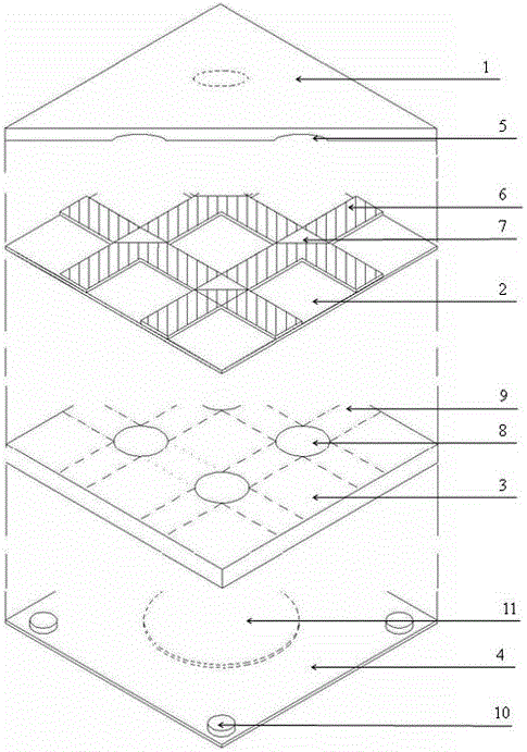
[0028] The upper cover plate is made of materials that are easy to make holes, have a small coefficient of thermal expansion, and can be mass-produced, and are preferably heat-insulating hard plastics, which can be formed by injection molding. The waveguide plate is made of a material that is easy to make smooth triangular through holes, preferably the same material as the upper cover plate and is formed by injection molding. The mesh waveguide structure is made of ultraviolet photoresist. The main body of the inner core of the electro-wetting piston can be molded with ABS plastic, and the surface is completely formed by electroplating a metal conductive layer inside the electro-wetting drive through hole, and then the control electrode and circuit are prepared on the upper surface by corrosion method; all the conductive layers are wrapped with a layer of insulation The layer is preferably parylene with a thickness of 3 microns produced by a vacuum coating method; the hydrophob...

Embodiment 2

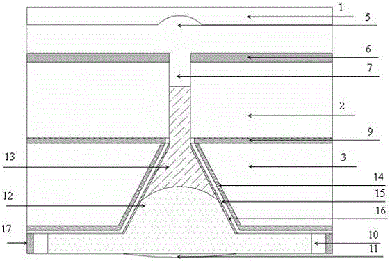
[0032] Since the micro-fluid cavity of the waveguide node is very small, it is difficult for the injected liquid to reach the designated position. The air cavity of the upper cover plate can be made into a small hole with an elastic film, and a pressure adjustment device is added outside the elastic film of the upper and lower cover plates. Pressurization makes the liquid column in the micropore stop at the designated position, and it can also be used as an auxiliary device for zero adjustment when the temperature changes too much. In special cases, the waveguide substrate and the mesh waveguide array on it can be integrally produced by injection molding, and the matching liquid can be omitted at the same time.


PUM


Abstract

The electro-wetting piston optical switch adopts the structure of upper cover plate (1), flat waveguide base (2), inner core of electro-wetting piston (3), and lower cover plate (4). Among them, a mesh waveguide structure (6) is set on the slab waveguide substrate (2), and a triangular or other shaped waveguide node micro-fluid cavity (7) is set at the waveguide intersection node; the electrowetting piston under the slab waveguide substrate (2) The core (3) is a flat plate with a conical or other shaped electro-wetting driving through hole (8) and a control circuit (9). The surface is provided with a conductive layer, an insulating layer and a hydrophobic layer; It is provided with a raised column (10) and a pressure balance hole (11) with an elastic film, which is glued with the inner core of the electro-wetting piston (3) with glue (17) to form an elastic liquid box for storing conductive fluid (12) and a refractive index matching liquid (13); on the upper cover plate, there are air pockets (5) corresponding to the waveguide node micro-liquid cavity (7) and the electro-wetting drive through hole (8) one-to-one to provide air chamber and air pressure.

Description

technical field [0001] The invention relates to a novel electronically controlled piston type optical switch structure and its working principle, belonging to the technical field of optical communication. Background technique [0002] The development trend of network photonics in China's optical communication market will continue to extend to the user end. It is only a matter of time before FTTH is popularized. The era of all-optical communication networks is coming. With the increasing demand for optical communication bandwidth, future optical networks not only need to support large-capacity transmission, but also need to increase switching capacity, and all-optical switching technology is the key to further increase switching capacity and is the development trend of future all-optical networks . In the all-optical network, the optical add-drop multiplexing device (OADM) and the optical cross-connect (OXC) are indispensable network node devices, and the large-capacity opti...

Claims


Application Information

Patent Timeline
Patent Type & Authority Patents(China)
IPC IPC(8): G02B26/02
Inventor 陈陶梁忠诚徐荣青
Owner NANJING UNIV OF POSTS & TELECOMM
Why Eureka
Try Eureka