
Electronic fence based on real-time geographic position

A technology of electronic fence and geographic location, applied in the direction of electrical alarms, instruments, alarms, etc., can solve the problem that the data storage format of the electronic fence is not optimized, the correct judgment and transmission of information cannot be guaranteed, and the geographic location cannot be located in real time. problems, to achieve the effect of short response time, high reliability and good management

Inactive Publication Date: 2013-07-03
TERRA DIGITAL CREATING SCI & TECH BEIJING CO LTD
View PDF5 Cites 35 Cited by
  • Summary
  • Abstract
  • Description
  • Claims
  • Application Information

AI Technical Summary

Problems solved by technology

Its scope of application is very limited and cannot be connected to other custom devices
[0005] 2. The data storage format of the electronic fence has not been optimized, so the correct judgment and transmission of information cannot be guaranteed for a large number of concurrent users
[0006] 3. All adopt GPS positioning method, indoors and equipment without GPS module can not receive satellite signals, so it is impossible to locate the geographical location of its monitoring object in real time

Method used


Image

  • Electronic fence based on real-time geographic position
  • Electronic fence based on real-time geographic position
  • Electronic fence based on real-time geographic position

Examples


Embodiment 1

[0031] The specific implementation of the present invention will be described in detail below in conjunction with the drawings and specific embodiments.

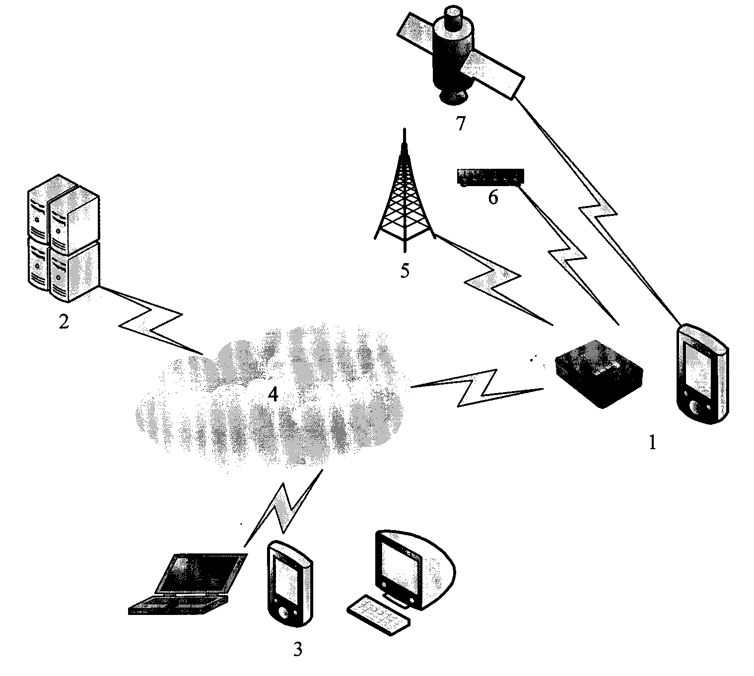
[0032] See attached figure 1 This is the hardware layout of the system. This system mainly includes terminal equipment 1, server 2, client 3. Terminal equipment 1 obtains relevant information through base station 5, WIFI 6, positioning satellite 7, and through the Internet (including mobile Internet and Internet) 4 Realize communication with server 2.

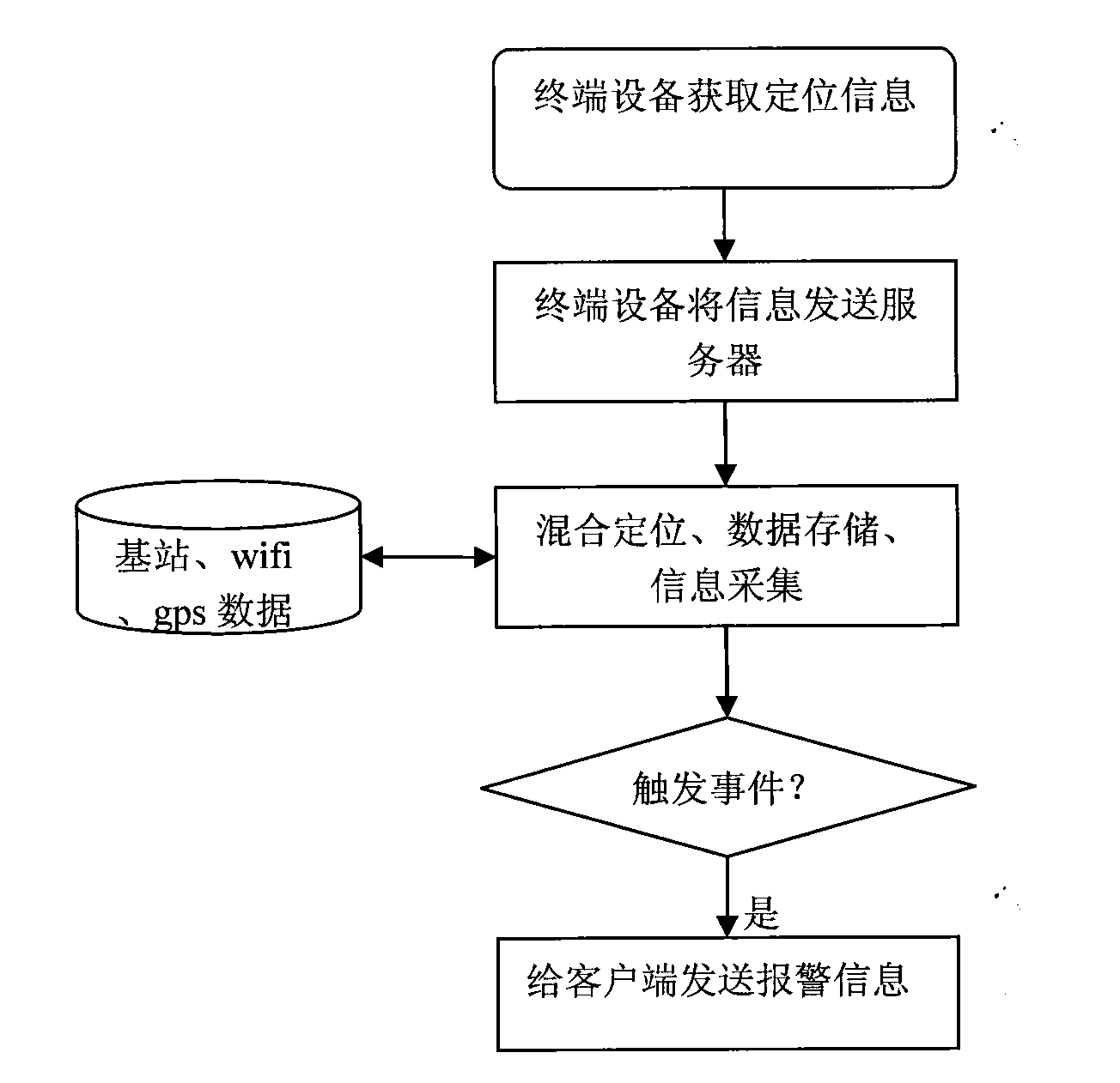
[0033] See attached figure 2 , Set up a three-dimensional scene on the server 2, the terminal device 1 transmits the relevant information Internet 4 to the server 2 to receive, and the server 2 performs positioning based on the information transmitted by the terminal device 1. The positioning method adopts a hybrid positioning method. The input data sources include gps, wifi Base station data, cell phone base station data. The above three types of data are combined to enhance th...

Embodiment 2

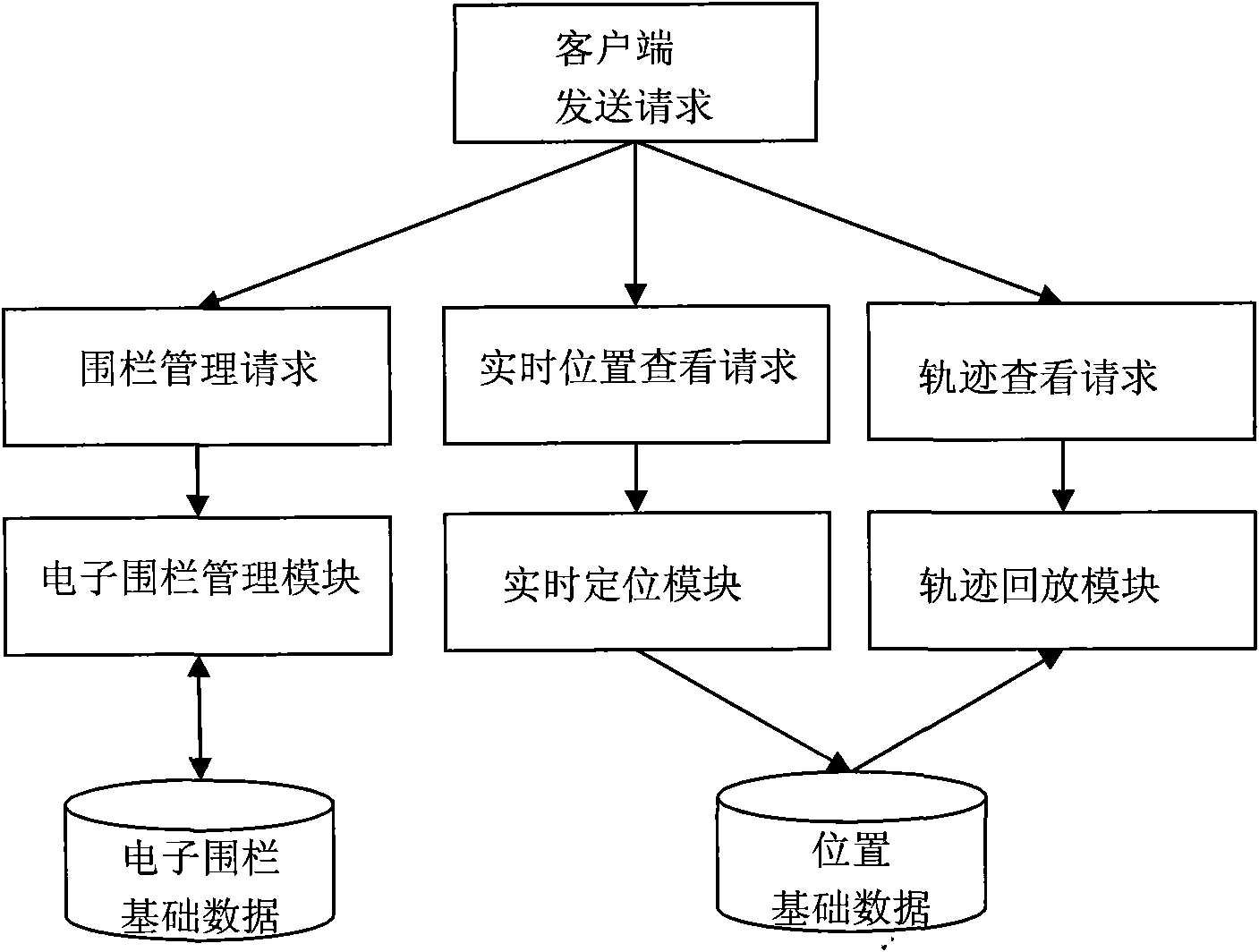
[0047] This embodiment provides an electronic fence system. This electronic fence system includes a system positioning query service platform and a terminal. The positioning query service platform includes an electronic fence module, a hybrid positioning module, a track playback module, and a user management module. The terminal equipment includes But it is not limited to mobile phones, GPS devices, and laptops connected to wireless networks. The client can instantly query the real-time geographic location of the monitored object by means of text messages; it can also log on to the system service operator’s website to query the user’s PC for related information.

[0048] The client can manage the electronic fence in many ways. When setting up an electronic fence, there are a variety of parameters to choose from: fence effective time limit, fence alarm type, monitored terminal device model, custom transmission protocol, and alarm information.

[0049] For example, for a dangerous g...


PUM


Abstract

The invention discloses an electronic fence based on a real-time geographic position. A system truly restores effects of the electronic fence in a computer based on a geographic information system, and information relevant to positioning is acquired by handheld terminal equipment efficiently in a multipath manner. A monitored object transmits the information to a server in a time interval, the server positions the monitored object through mixed positioning and judges whether the monitored object triggers a fence event to decide to transmit alarm information to a monitor, so that efficient monitoring management is achieved.

Description

Technical field [0001] The invention relates to an electronic fence based on geographic location, in particular to an electronic fence based on real-time geographic location, supporting high concurrency, and using hybrid positioning. Background technique [0002] At present, the electronic fence is a tangible perimeter anti-theft alarm system, which is composed of an electronic fence host and a front-end detection fence. The electronic fence host generates and receives high-voltage pulse signals. It can generate alarm signals when the front-end detection fence is in contact, short-circuit, or open-circuit conditions, and send the intrusion signal to the security alarm center; the front-end detection fence is composed of rods and metal wires and other components The tangible perimeter. Electronic fence is a kind of active intrusion prevention fence, which can counterattack the intrusion attempt, repel the intruder, delay the intrusion time, but does not threaten human life. At t...

Claims


Application Information

Patent Timeline
IPC IPC(8): G08B13/22G08B25/00
Inventor 刘俊伟沈亮柴崎唐莉萍
Owner TERRA DIGITAL CREATING SCI & TECH BEIJING CO LTD
Learn More