Circular polarization antenna

A technology of circularly polarized antennas and antenna elements, which is applied in antennas, slot antennas, antenna unit combinations with different polarization directions, etc., can solve the problems of dipole antenna reception, data loss, and change transmission of vertically polarized waves, etc., to achieve The effect of high antenna gain and large antenna bandwidth

A technology of circularly polarized antennas and antenna elements, which is applied in antennas, slot antennas, antenna unit combinations with different polarization directions, etc., can solve the problems of dipole antenna reception, data loss, and change transmission of vertically polarized waves, etc., to achieve The effect of high antenna gain and large antenna bandwidth

CN103187616AInactive Publication Date: 2013-07-03MEDIATEK INC

Image

  • Circular polarization antenna
  • Circular polarization antenna
  • Circular polarization antenna

Examples


Embodiment Construction

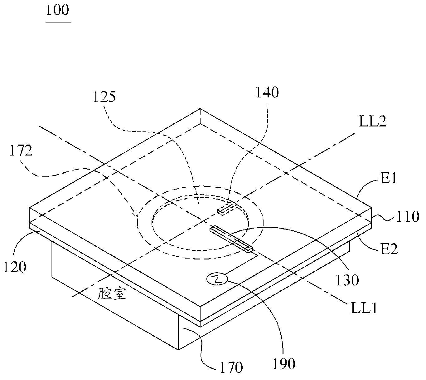
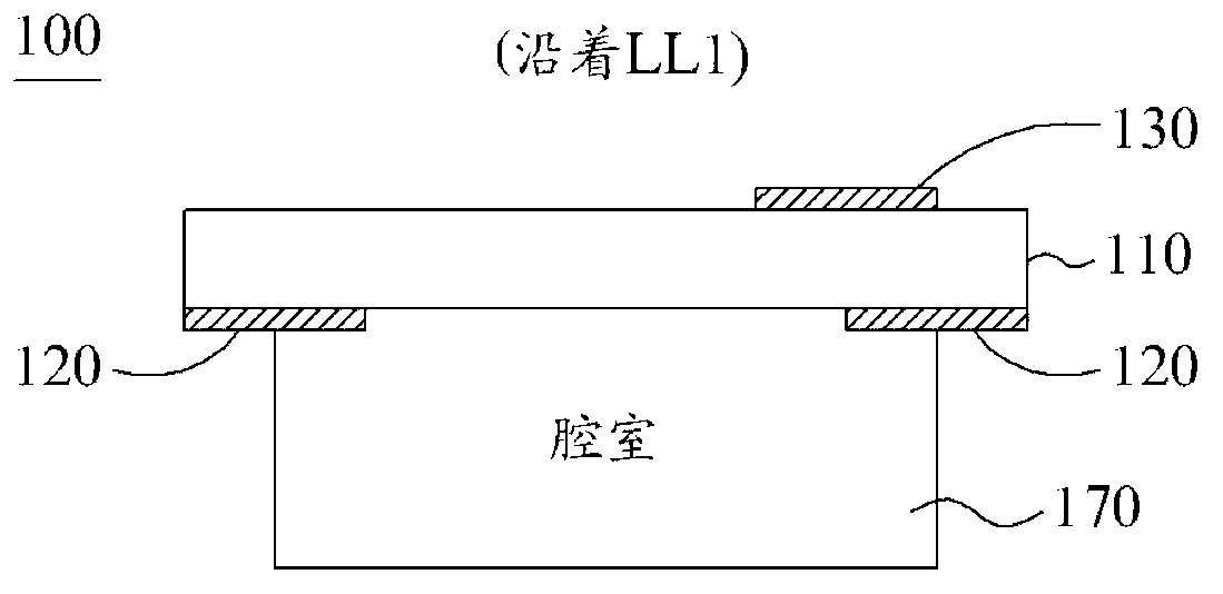
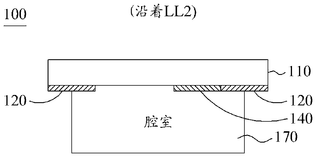
[0030] Figure 1A It is a perspective view showing a circularly polarized antenna 100 according to an embodiment of the present invention. Figure 1B is a cross-sectional view of the circularly polarized antenna 100 along the line LL1 according to this embodiment of the present invention. Figure 1C It is a cross-sectional view of the circularly polarized antenna 100 along another line LL2 according to this embodiment of the present invention. like Figure 1A , Figure 1B and Figure 1C As shown, the circularly polarized antenna 100 may include: a substrate 110 , a ground plane 120 , a feeding element (Feeding Element) 130 , a tuning stub (Tuning Stub) 140 and a cavity structure (Cavity Structure) 170 . The substrate 110 may be an FR4 substrate with a dielectric constant (Dielectric Constant) equal to 4.3 and a substrate thickness of 0.6 mm. The ground plane 120, the feed element 130, and the tuning stub 140 may be made of metal, such as silver or copper.

[0031] The base...


PUM


Abstract

A circular polarization antenna includes a substrate, a ground plane, a tuning stub, a feeding element, and a cavity structure. The substrate has a first surface and a second surface. The feeding element is disposed on the first surface of the substrate. The ground plane is disposed on the second surface of the substrate and has a hole. The tuning stub is disposed on the second surface of the substrate and connected to the edge of the hole. The cavity structure is connected to the ground plane and configured to reflect an electromagnetic wave. The circular polarization antenna has higher antenna gain or higher antenna beamwidth.

Description

technical field [0001] The present invention relates to a circular polarized antenna (Circular Polarization Antenna), in particular to a circular polarized antenna with high antenna gain (Antenna Gain). Background technique [0002] In wireless data transmission, antennas play an important role in transmitting and receiving electromagnetic waves. Normally, the antenna should provide an omnidirectional (Omni-Directional) radiation pattern (Radiation Pattern) in the azimuth direction (Azimuth Direction), and provide a null point (Null) pattern directly above. Therefore, rod-like antennas, such as dipole antennas, are generally suitable for receiving and transmitting vertically polarized waves, and thus are widely used in today's communication devices. [0003] In a wireless communication system, data signals may be reflected by many surrounding objects, therefore, these reflected waves (Reflected Waves) and the original data signal will produce constructive or destructive mix...

Claims


Application Information

Patent Timeline
03 Jul 2013
Publication
CN103187616A
IPC
H01Q1/36; H01Q1/48; H01Q15/16; H01Q21/24
CPC
H01Q21/24; H01Q13/18; H01Q21/061
Inventors
洪国锋; 谢士炜