
Real-time self-diagnosis method in operation of motor of electric power steering system

A technology of electric power steering and power-assisted motors, which is applied in the direction of electrical components, emergency protection circuit devices, etc., can solve problems such as large time delay, short circuit or open circuit of wiring harness, bearing or gearbox failure, etc., so as to improve cost performance, ensure safety, and reduce risk effect

Active Publication Date: 2013-07-03
LIANCHUANG AUTOMOBILE ELECTRONICS
View PDF6 Cites 27 Cited by
  • Summary
  • Abstract
  • Description
  • Claims
  • Application Information

AI Technical Summary

Problems solved by technology

[0004] 1. One or more coils of the motor are short-circuited or open-circuited
[0005] 2. The wiring harness of the motor is connected incorrectly, the wiring harness is short-circuited or open-circuited
[0006] 3. Bearing or gearbox failure
[0011] Generally speaking, some motor driver chips provide the motor phase line short-circuit fault diagnosis function, but the short-circuit fault diagnosis function provided by the motor driver chip often has a relatively long time delay, and the fault cannot be judged in time and quickly after the fault occurs.
In addition, the motor driver chip does not provide the function of diagnosing the open circuit of the motor phase line
Moreover, even if the motor drive chip can quickly determine the fault, when a short circuit occurs between the motor phase lines, the motor drive circuit is turned off, but due to the existence of the motor’s back electromotive force, a current can be formed between the motor phase lines, which will still cause the electric booster Steering system locked

Method used


Image

  • Real-time self-diagnosis method in operation of motor of electric power steering system
  • Real-time self-diagnosis method in operation of motor of electric power steering system
  • Real-time self-diagnosis method in operation of motor of electric power steering system

Examples


Embodiment Construction

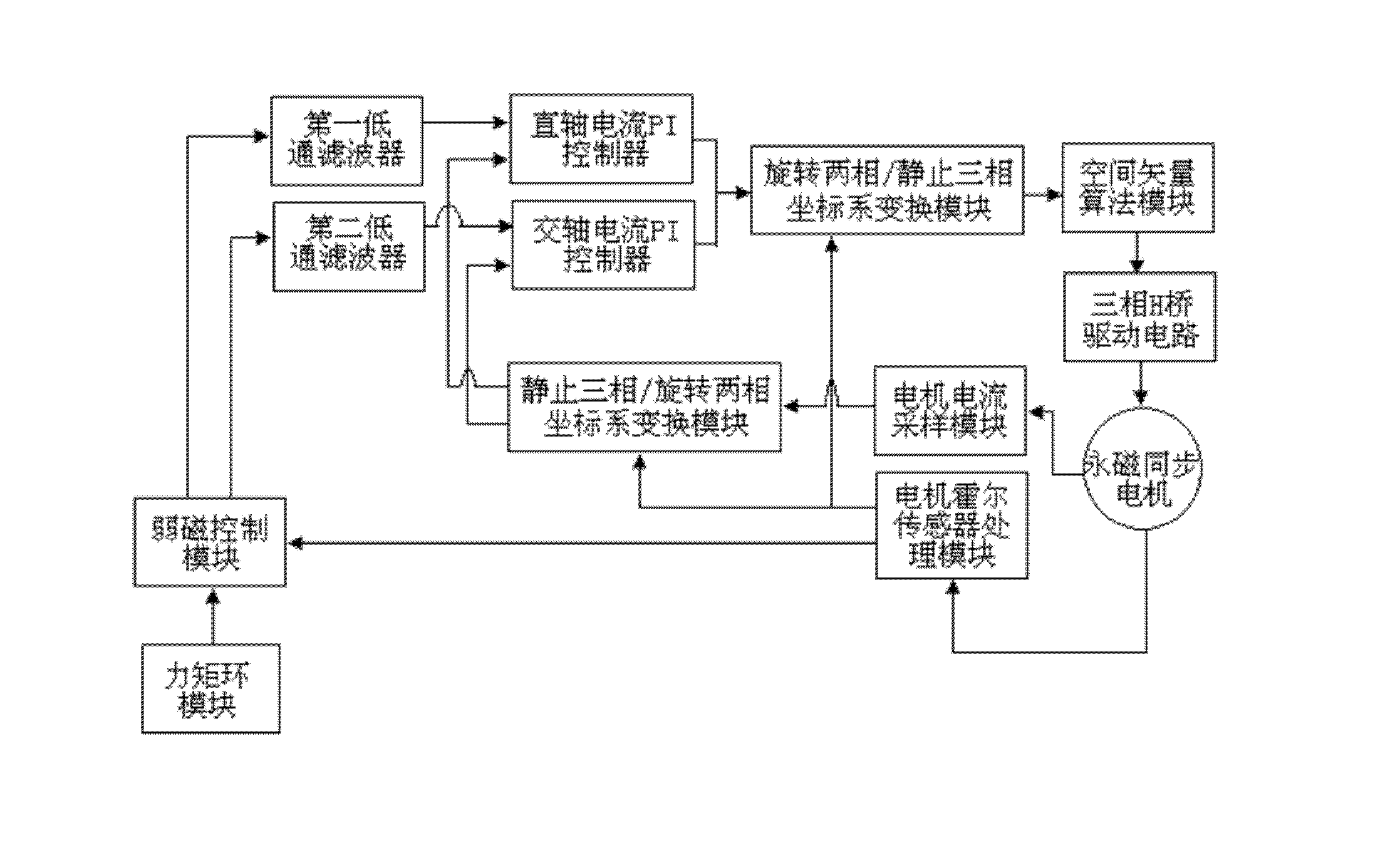
[0027] The control block diagram of the permanent magnet synchronous motor in the electric power steering system is shown in figure 1 shown, which includes:

[0028] The torque loop module sends motor assist torque commands to realize basic assist control, motor inertia compensation, friction damping compensation, back alignment and active damping control.

[0029] The field-weakening control module provides a direct-axis d-axis current command and a quadrature-axis q-axis current command according to the motor assist torque command and the motor speed obtained through the motor Hall sensor processing module.

[0030] The first low-pass filter filters the direct-axis d-axis current command signal.

[0031] The second low-pass filter filters the quadrature-axis q-axis current command signal.

[0032] The direct-axis current PI controller converts the filtered direct-axis d-axis current command signal and the motor three-phase current collected by the motor current sampling mo...


PUM


Abstract

The invention discloses a real-time self-diagnosis method in operation of a motor of an electric power steering system. Two phase line relays are installed on phase lines of the motor of the electric power steering system, an estimation value of control voltage Vd of a direct shaft d, an estimation value of control voltage Vq of an alternating shaft q, an estimation value of current id of the direct shaft d and an estimation value of current iq of the alternating shaft q are respectively estimated based on a motor control model, each obtained estimation value is compared to a corresponding practical controlling value, and differential values serve as bases which are used for judging whether motor faults exist or not; and when the motor faults are confirmed to exist, the two phase lines installed on the phase lines of the motor are cut off, current between accesses of the phase lines of the motor is cut off, a motor return circuit is prevented from generating current, and the electric power steering system is switched to a mechanical steering system. The real-time self-diagnosis method can detect whether a short circuit or open circuit fault exists in the electric power steering system or not rapidly, and the circumstances that the steering system is locked and power assisting is disordered can be prevented.

Description

technical field [0001] The invention relates to the field of automobile electric power steering system (EPS), in particular to a method for real-time self-diagnosis of motor operation of the electric power steering system. Background technique [0002] The EPS steering system is an automotive safety-related component, which has extremely high requirements on safety performance. The booster motor (in the following description, the "motor" referred to refers to the "power booster motor") adopts a permanent magnet synchronous motor and is driven by a three-phase inverter full bridge. When the power assist motor has a short circuit between phases, an open circuit of the phase line, or a fault in the drive circuit, it may lead to high-risk events such as steering system lockup and power assist confusion. [0003] The main faults of the motor are as follows: [0004] 1. One or more coils of the motor are short-circuited or open-circuited. [0005] 2. The wiring harness of the m...

Claims


Application Information

Patent Timeline
IPC IPC(8): H02H7/08H02H7/085H02H7/09
Inventor 唐文金灿龙田佰辉施雯
Owner LIANCHUANG AUTOMOBILE ELECTRONICS
Learn More