Power supply control device of magnetic valve flow in anaesthesia machine and method thereof

A technology of power control device and solenoid valve, which is applied in the direction of output power conversion device, adjustment of electric variable, control/regulation system, etc., to achieve the effect of eliminating tube pressure drop and heating problems, simple structure, and reducing the risk of single failure

Active Publication Date: 2013-07-03
BEIJING AEONMED
View PDF6 Cites 10 Cited by
  • Summary
  • Abstract
  • Description
  • Claims
  • Application Information

AI Technical Summary

Problems solved by technology

[0008] The purpose of the present invention is to overcome the defects and deficiencies of the prior art, and provide a power supply control device and method for the flow of a solenoid valve in an anesthesia machine. The device controls the working state of the entire circuit by controlling whether the power supply chip outputs a voltage signal to the solenoid valve. , which reduces the risk of a single failure that may exist in the prior art and the problems of tube pressure drop and tube heating that exist when the MOS tube is used as a switch

Method used


Image

  • Power supply control device of magnetic valve flow in anaesthesia machine and method thereof
  • Power supply control device of magnetic valve flow in anaesthesia machine and method thereof
  • Power supply control device of magnetic valve flow in anaesthesia machine and method thereof

Examples


Embodiment Construction

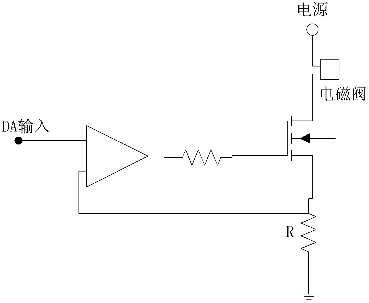
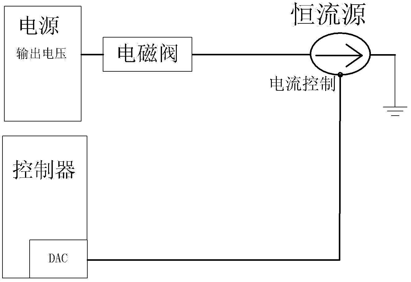
[0031] The technical principle of the present invention is to control the working state of the whole device by controlling whether the power supply chip outputs a voltage signal to the solenoid valve.

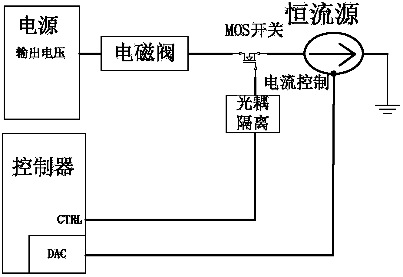
[0032] When the power chip used has an enable signal control terminal, the enable signal can control whether the power chip has an output, and the signal generation controller circuit outputs an enable signal for controlling the power supply of the solenoid valve, so that the output of the power chip can be controlled. The power enable signal is valid, the power chip outputs voltage to supply power to the solenoid valve, the enable signal is invalid, and the power chip does not output voltage.

[0033] When the power chip used does not have an enabling control terminal, the output of the power chip is controlled through a power switch tube or a relay. The power switch tube can withstand a large current, the leakage current is small, and has good saturation conduction and cut-of...


PUM


Abstract

The invention discloses a power supply control device of a magnetic valve flow in an anaesthesia machine. The power supply control device of the magnetic valve flow in the anaesthesia machine comprises a signal generation controller circuit, a power supply chip, a magnetic valve, a constant flow source circuit and a power supply chip input control circuit, wherein the power supply chip input control circuit is used for sending a signal output by the signal generation controller circuit to the power supply chip, and the power supply chip outputs voltage to the magnetic valve. The signal generation controller circuit directly controls a size of constant flow source current through controlling a ratio relationship between a signal and a constant flow source, so that the fact that the constant flow source controls the magnetic valve flow is achieved. The power supply control device reduces the risk of a single fault in the prior art and solves the problems of pipe pressure reducing and heating due to the fact that an MOS pipe is adopted to be served as a control power source switch. The power supply control device is simple in structure, safe by the adoption of opto-isolator protection, high in control accuracy and suitable for fields of industrial control.

Description

technical field [0001] The invention relates to the field of electromagnetic valve flow control in anesthesia machines, in particular to a power supply control device and method for electromagnetic valve flow in anesthesia machines. Background technique [0002] Solenoid valves are usually used in anesthesia machines to precisely control the flow of gases and liquids. The solenoid valve consists of a solenoid coil and a magnetic core, and is a valve body containing one or several holes. When the electromagnetic coil is energized or de-energized, the operation of the magnetic core will cause the fluid to pass through the valve body or be cut off, so as to achieve the purpose of changing the direction of the fluid. In order to ensure the stability of the flow rate of the solenoid valve in the anesthesia machine, it is usually controlled by a constant current source circuit. [0003] The constant current source circuit is also called the current mirror circuit. The essence of ...

Claims


Application Information

Patent Timeline
Patent Type & Authority Applications(China)
IPC IPC(8): H02M3/155
Inventor 何敏杰徐文张耀东
Owner BEIJING AEONMED
Why Eureka
Try Eureka