Laser welding method for medium steel plates

A technology of laser welding and thick steel plates, which is applied in laser welding equipment, welding equipment, metal processing equipment, etc., can solve the problems that the weld seam cannot meet the design requirements and can not achieve one-time welding completion, etc.

Inactive Publication Date: 2013-07-10
上海第一机床厂有限公司
View PDF5 Cites 5 Cited by
  • Summary
  • Abstract
  • Description
  • Claims
  • Application Information

AI Technical Summary

Problems solved by technology

For medium-thick steel plates with a thickness of 5 to 18 mm, one-time welding cannot be achieved, and the weld seam cannot meet the design requirements

Method used


Image

  • Laser welding method for medium steel plates
  • Laser welding method for medium steel plates
  • Laser welding method for medium steel plates

Examples


Embodiment Construction

[0019] The specific implementation of the laser welding method for medium and thick steel plates of the present invention will be described in detail below in conjunction with the accompanying drawings.

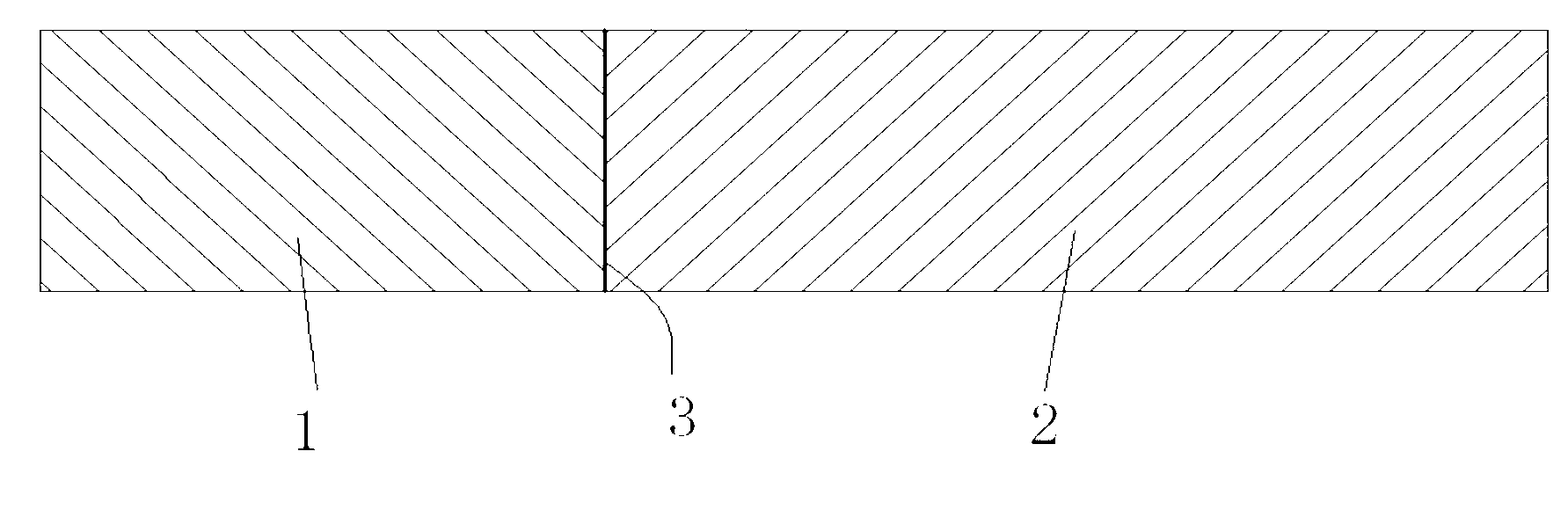
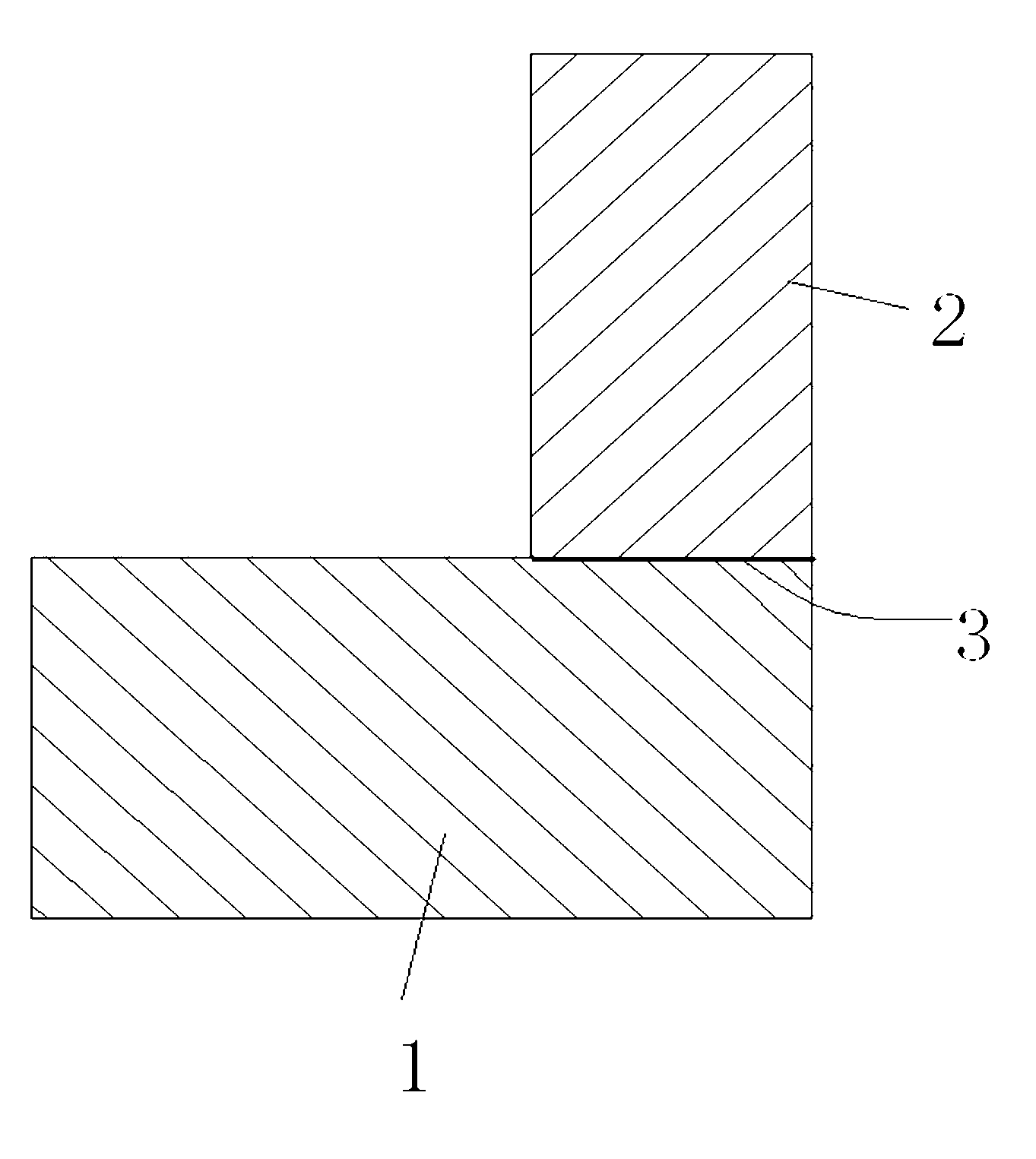
[0020] See attached figure 1 , 2 , 3. The thickness of the medium-thick steel plate is 5-18mm. The two steel plates 1 and 2 should be butt jointed or angled into a typical finished product as shown in the figure. The welding method is as follows:

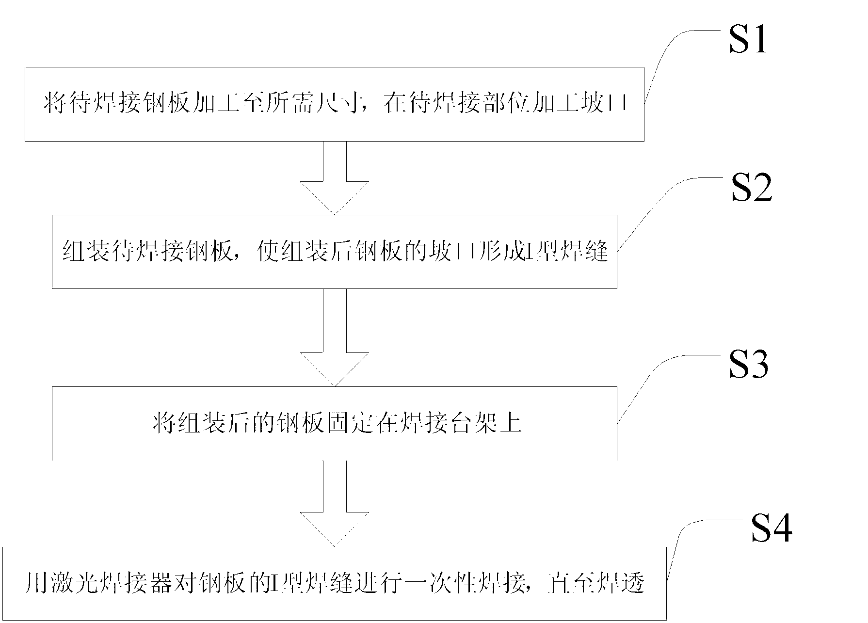
[0021] Step 1: Process the steel plates 1 and 2 to be welded to the required size, and process grooves on the parts to be welded (step S1 in the figure), and design different butt joints or fillet joints of the grooves according to different conditions of the steel plates to be welded Form (such as stepped joints, oblique butt joints, bottom-lock self-centering joints, etc.).

[0022] Step 2: Assemble the steel plates 1 and 2 to be welded so that the groove of the assembled steel plates forms an I-shaped weld 3 (step S2 in the fi...


PUM

PropertyMeasurementUnit
thicknessaaaaaaaaaa
poweraaaaaaaaaa

Abstract

The invention relates to the technical field of material welding, and discloses a laser welding method for medium steel plates with thicknesses of 5-18mm. The laser welding method includes firstly, processing to-be-welded steel plates in required sizes and chamfering at to-be-welded positions; secondarily, assembling the to-be-welded steel plates to enable chamfers of the assembled steel plates to form I-shaped welded joints; thirdly, fixing the assembled steel plates on a welding rack; and fourthly, performing one-time welding on the I-shaped welded joints of the steel plates by a laser welding apparatus until through welding is completed. Welded joints with thicknesses of 5-18mm can be formed through one-time welding by the aid of the laser welding apparatus, welding speed is greatly increased, welding contraction ranges from 0.1mm to 0.8mm, indexes such as welded joint strength, toughness and chemical component after welding can meet or are superior to the requirements on arc welding techniques of conventional filling welding materials.

Description

technical field [0001] The invention relates to the technical field of material welding, in particular to a laser welding method for medium-thick steel plates. Background technique [0002] With the rapid development of welding technology, welding technology has made great progress in recent years. As for the welding method of medium and thick plates, it has mainly experienced three development stages: manual arc welding, automatic arc welding, and automatic high-energy beam welding. Manual arc welding is mainly manual arc welding, which has slow welding speed, low efficiency, high work intensity, poor welding environment, and weld quality is related to the welder's skills. At present, it is only used in small workpieces and fields where automatic welding cannot be realized; automatic arc welding The representative of the welding method is submerged arc welding, which solves the shortcomings of low welding efficiency of manual arc welding, but its welding deformation is lar...

Claims


Application Information

Patent Timeline
Patent Type & Authority Applications(China)
IPC IPC(8): B23K26/26B23K26/42B23K26/24B23K26/70
Inventor 冷晓春龚宏伟李恩林金伟芳张亮
Owner 上海第一机床厂有限公司
Why Eureka
Try Eureka