Micro-vision hand-eye calibration method based on target motion

A microscopic vision and motion technology, applied in the field of microscopic vision hand-eye calibration based on target movement, can solve the problem that only two-dimensional position coordinates can be measured but cannot calibrate the relationship between the image coordinate increment and the relative position in three-dimensional space, and achieve Improved adaptability and usability, the effect of easy application

Inactive Publication Date: 2013-07-10
INST OF AUTOMATION CHINESE ACAD OF SCI
View PDF5 Cites 9 Cited by
  • Summary
  • Abstract
  • Description
  • Claims
  • Application Information

AI Technical Summary

Problems solved by technology

[0004] In order to solve the problem that microscopic vision in the prior art can only measure two-dimensional position coordinates and cannot calibrate the relationship between the image coordinate increment and the relative position in three-dimensional space, the purpose of the present invention is to provide a microscopic vision based on target motion Calibration systems and methods

Method used


Image

  • Micro-vision hand-eye calibration method based on target motion
  • Micro-vision hand-eye calibration method based on target motion
  • Micro-vision hand-eye calibration method based on target motion

Examples


Embodiment Construction

[0021] In order to make the object, technical solution and advantages of the present invention clearer, the present invention will be described in further detail below in conjunction with specific embodiments and with reference to the accompanying drawings.

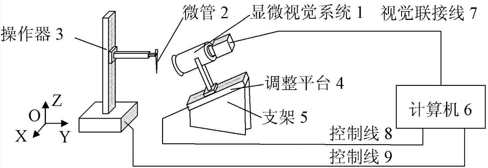
[0022] According to an aspect of the present invention, propose a kind of micro vision calibration system, such as figure 1 As shown, the microscopic vision calibration system includes: a microscopic vision system 1, a microtube 2, an operator 3, an adjustment platform 4, a bracket 5, and a computer 6, wherein:

[0023] The adjustment platform 4 is installed on a support 5 for driving the microscopic vision system 1 to move, and the upper part of the support 5 is inclined;

[0024] The microscopic vision system 1 is installed on the adjustment platform 4, so that there is an inclination between the microscopic vision system 1 and the lower installation plane of the support 5;

[0025] The micropipe 2 is installed on the ...


PUM


Abstract

The invention discloses a micro-vision calibration system and a micro-vision calibration method based on target motion. Calibration between the micro-vision calibration system and an operating device is achieved by utilizing at least twice relative motion of a target in a clear imaging plane. First, the operating device drives a micro-tube to enter a visual field of the micro-vision calibration system, a coordinate of the operating device is adjusted to enable the micro-vision calibration system to be capable of acquiring a clear image at the tail end of the micro-tube, and an image coordinate and an operating device coordinate at the tail end of the micro-tube are recorded. Then, on the premise that the image at the tail end of the micro-tube is kept to be clear, the operating device drives the micro-tube to perform twice relative motion in the clear imaging plane, and the image coordinate and the operating device coordinate at the tail end of the micro-tube are recorded. An image jacobian matrix is calculated by utilizing a least square method according to changes of the micro-tube image coordinate and the operating device coordinate. The micro-vision hand-eye calibration method based on the target motion is convenient to apply, on-line calibration of the micro-vision calibration system can be achieved, and the adaptability and the availability of micro-operation under the guiding of micro-vision can be remarkably improved.

Description

technical field [0001] The invention belongs to the microscopic vision measurement and control in the technical field of robot micro-operation, in particular to a microscopic vision hand-eye calibration method based on target motion. Background technique [0002] At present, in the field of micro-manipulation, microscopic vision is often used to measure the position and attitude of the target in the plane. Due to the small depth of field and small field of view of microscopic vision, in order to obtain the spatial coordinates of the target, the optical axis of the microscopic vision system needs to be parallel to a coordinate axis of the three-dimensional space coordinate system. In this way, the use of microscopic vision can only obtain the two-dimensional position coordinates of the target in three-dimensional space (see literature: X.Zeng, X.Huang, M.Wang, Micro-assembly of micro parts using uncalibrated microscopes visual servoing method, Information Technology Journal,...

Claims


Application Information

Patent Timeline
Patent Type & Authority Applications(China)
IPC IPC(8): B25J13/08
Inventor 徐德李福东张正涛史亚莉李海鹏张大朋
Owner INST OF AUTOMATION CHINESE ACAD OF SCI
Why Eureka
Try Eureka