V-shaped empennage device suitable for sea and air across amphibious unmanned aerial vehicle

An unmanned aerial vehicle and tail wing technology, applied in the tail wing field, can solve the problems of increasing the weight of the body, increasing the resistance of part of the tail wing, and the failure of the steering gear, and achieving the effects of simplifying the structure, reducing the weight of the structure, and reducing the resistance.

Inactive Publication Date: 2013-07-10
BEIHANG UNIV
View PDF7 Cites 16 Cited by
  • Summary
  • Abstract
  • Description
  • Claims
  • Application Information

AI Technical Summary

Problems solved by technology

[0006] At present, the tail fins used on UAVs generally include horizontal tail fins and vertical tail fins. There are generally two horizontal tail fins. The structure is more complicated, which increases the weight of the entire body and increases the resistance of the tail fin.
On the other hand, the drive steering gear of the tail control rudder surface of the traditional UAV does not consider water sealing. When the operating environment changes (air environment to water body environment), the steering gear will fail due to water immersion or wetting, thus hindering The application of unmanned aerial vehicles in unstructured and variable environmental conditions

Method used


Image

  • V-shaped empennage device suitable for sea and air across amphibious unmanned aerial vehicle
  • V-shaped empennage device suitable for sea and air across amphibious unmanned aerial vehicle
  • V-shaped empennage device suitable for sea and air across amphibious unmanned aerial vehicle

Examples


Embodiment Construction

[0063] The present invention will be further described in detail below in conjunction with the accompanying drawings.

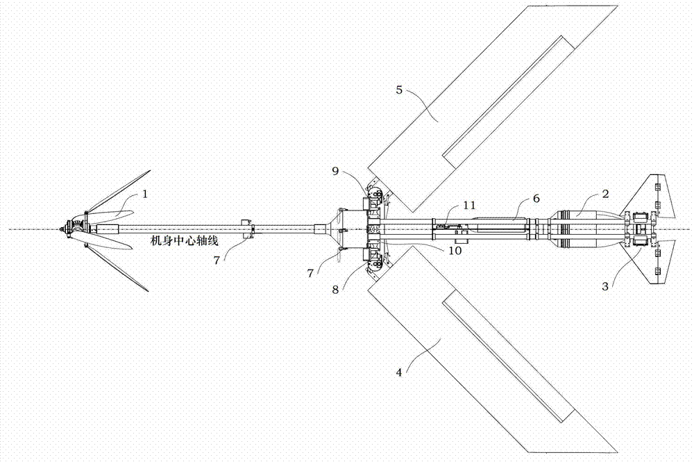
[0064] A top view structure suitable for amphibious UAVs across sea and air such as figure 1 As shown, the UAV includes a coaxial anti-propeller assembly 1, an underwater propulsion assembly 2, a V-tail assembly 3 (hereinafter also referred to as a V-tail device), a left wing assembly 4, a right wing assembly 5, and a beam assembly 6 , Water and air bag erection assembly 7, left wing drive assembly 8, right wing drive assembly 9, folding wing support body 10 and folding and unfolding conversion assembly 11;

[0065] Wherein, the left wing assembly 4, the left wing drive assembly 8, the right wing assembly 5, the right wing drive assembly 9 and the folding wing support body 10 constitute the foldable wing part of the drone;

[0066] Wherein, the left wing assembly 4 has the same structure as the right wing assembly 5, and is installed symmetrically with the ...


PUM


Abstract

The invention discloses a V-shaped empennage device suitable for a sea and air across amphibious unmanned aerial vehicle. The V-shaped empennage device comprises a left balance wing, a right balance ring, a left control rudder, a right control rudder, a left rudder pedal, a right rudder pedal, a first empennage steering engine, a second empennage steering engine, a left empennage connecting rod, a right empennage connecting rod, a front empennage bracket, a rear empennage bracket, a front empennage connecting rack and a rear empennage connecting rack, wherein the front empennage bracket, the rear empennage bracket, the front empennage connecting rack and the rear empennage connecting rack are in parallel and opposite to one another and are arranged on the left empennage connecting rod and the right empennage connecting rod; the left rudder pedal is arranged on the left control rudder; the right rudder pedal is arranged on the right control rudder; the first empennage steering engine is arranged on the left balance wing; and the second empennage steering engine is arranged on the right balance wing. Each steering engine of the empennage control rudder is provided with a sealing shell, so that the steering engine also can normally work under underwater navigation; forward power is provided by an underwater propeller, and the rudder angle of the V-shaped empennage control rudder is regulated to realize flotation, submergence and turning motion of the unmanned aerial vehicle; and moreover, during air flight, the rudder angle of the control rudder is regulated to realize climbing, diving and turning motion of the unmanned aerial vehicle.

Description

technical field [0001] The invention relates to a tail fin for an unmanned aerial vehicle, more particularly, a V-shaped tail fin device suitable for an amphibious unmanned aerial vehicle across the sea and air. Background technique [0002] UAV is the abbreviation of unmanned aerial vehicle, and the English abbreviation is UAV (Unmanned Aerial Vehicle). [0003] The most important requirement for the design of the UAV is to be as light as possible while the fuselage system is strong enough. However, UAVs under various mission load requirements leave very limited space and quality quotas for motion transmission mechanisms. It is necessary to flexibly and efficiently convert basic engineering driving motions, such as high-speed rotation, into favorable controlled motions. The basic aviation transmission methods include direct drive, proportional amplification drive, electric servo drive and hydraulic servo drive. [0004] UAV is an unmanned aircraft operated by radio remote...

Claims


Application Information

Patent Timeline
IPC IPC(8): B64C5/10B60F5/02
Inventor 王田苗杨兴帮梁建宏吴海亮曾庆儒
Owner BEIHANG UNIV
Why Eureka
Try Eureka