Large-treatment capacity photocatalytic wastewater degradation reactor thoroughly depleting secondary ozone

A technology of wastewater degradation and treatment capacity, applied in the fields of oxidized water/sewage treatment, chemical instruments and methods, water/sewage multi-stage treatment, etc., can solve the problems of energy consumption, waste of energy, unsatisfactory and other issues

Inactive Publication Date: 2013-07-10
NINGBO UNIV
View PDF4 Cites 3 Cited by
  • Summary
  • Abstract
  • Description
  • Claims
  • Application Information

AI Technical Summary

Problems solved by technology

[0030] The operation of the wastewater catalytic degradation reactor needs to consume energy. Therefore, the operator will definitely hope that when the wastewater degradation reaction reaches the end, it can be impartial, neither too early nor too late to stop the continuous injection into the reactor. Energy; if the time to stop injecting energy is too early, the degradation of wastewater will not be complete; and if the end of the reaction has already been reached, but still continue to inject energy into the reactor, it is undoubtedly a waste of precious energy
As the structure of the CN102260003A scheme of the technical background of this case, any instant information cannot be given to the terminal moment of the wastewater degradation reaction, so, the terminal point of the wastewater degradation reaction can only be estimated by experience; and the terminal point of the wastewater degradation reaction is estimated by experience, That is obviously unsatisfactory; then, how to make an immediate information output that is neither advanced nor delayed for the end point of the wastewater degradation reaction, and immediately shut down the energy input to the reactor at just the right moment is a technology that cannot be underestimated Threshold, this is the seventh question

Method used


Image

  • Large-treatment capacity photocatalytic wastewater degradation reactor thoroughly depleting secondary ozone

Examples


Embodiment Construction

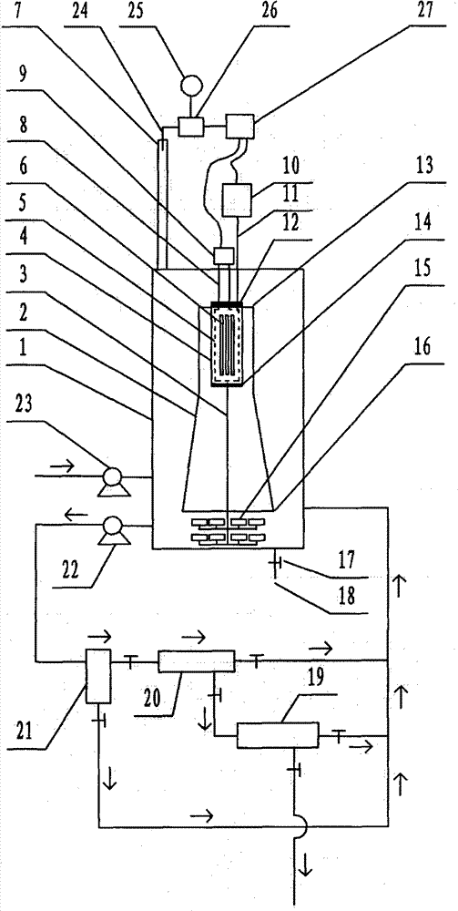
[0075] exist figure 1 In the shown embodiment of the case, the main component of the reactor is a hollow container 1, and the outline of the container 1 is in the shape of a cube, a cuboid, a cylinder, an ellipse, a polygon, a sphere or an ellipsoid. Body shape, the structure of the reactor also includes a microporous aeration head 15, the number of the microporous aeration head 15 is more than one, and the installation position of the microporous aeration head 15 is in the lower area of ​​the inner cavity of the container , the label 15 in the legend only refers to the individual microporous aeration head, and the quartz tube 4, which is installed in the inner cavity of the container 1, and the two ends of the quartz tube 4 are provided with a sealing cap 12 and 14, the plugging caps 12 and 14 respectively located at the two ends of the quartz tube 4 are provided with ventilation interfaces, and the electrodeless ultraviolet lamp 6 is rod-shaped, ring-shaped, spherical, starf...


PUM

PropertyMeasurementUnit
pore sizeaaaaaaaaaa
pore sizeaaaaaaaaaa
pore sizeaaaaaaaaaa

Abstract

The invention relates to a large-treatment capacity photocatalytic wastewater degradation reactor thoroughly depleting secondary ozone, belonging to the technical field of wastewater treatment. In the related art, the problems of loss of a catalyst, waste of microwave energy, smaller single-tank capacity, insufficient internal liquid cycling intensity, non-complete ozone utilization, difficulty in distinguishing the time of the end point of degradation reaction and the like exist, and the scheme is designed against the series of the problems. The structure of the scheme is as follows: a microwave irradiation airspace is limited; an ozone-containing air bubble flow is bunched and led to a key reaction area; the structure adopts an external cascaded three-stage backwashing type filter to achieve stage-by-stage interception against micro-particles of the catalyst; materials for a filter element of the structure are not limited any more; an ozone sensor is further assembled at a tail gas exhaust port of the structure, and an output electrical signal is transmitted to a power supply controller linked with a magnetron and an air pump; and through the architecture, energy injection can be immediately closed when the degradation reaction achieves an end point, and the process of the excess ozone can be immediately terminated.

Description

technical field [0001] The invention relates to a large-capacity photocatalytic wastewater degradation reactor with completely depleted secondary ozone, belonging to the technical field of CO2F wastewater treatment. Background technique [0002] Microwave photocatalytic degradation treatment technology, as an effective harmless treatment technology for industrial wastewater containing organic pollutants, has attracted much attention in recent years. [0003] Regarding the microwave photocatalytic degradation technology, as an example, refer to the Chinese patent application with publication number CN102260003A. [0004] The Chinese patent application with the publication number CN102260003A uses microwaves as the excitation source to excite the electrodeless ultraviolet lamp to emit ultraviolet rays, and irradiates the suspension mixed with photocatalyst titanium dioxide inside the liquid. The electrodeless ultraviolet lamp is shrouded and protected by a quartz tube. , an a...

Claims


Application Information

Patent Timeline
Patent Type & Authority Applications(China)
IPC IPC(8): C02F9/08C02F1/30C02F1/32C02F1/78C02F1/44
Inventor 李榕生任元龙葛从辛李天华周汉坤孙杰王冬杰干宁孔祖萍
Owner NINGBO UNIV
Why Eureka
Try Eureka