
Debris flow diversion dam capable of automatically distributing drainage quantity and silt stopping quantity and design method of debris flow diversion dam

An automatic distribution and diversion dam technology, which is applied in the direction of dams, river improvement, sea area engineering, etc., to achieve the effects of saving investment, preventing secondary disasters, and reducing the height of the dam body

Active Publication Date: 2015-03-11
INST OF MOUNTAIN HAZARDS & ENVIRONMENT CHINESE ACADEMY OF SCI
View PDF4 Cites 0 Cited by
  • Summary
  • Abstract
  • Description
  • Claims
  • Application Information

AI Technical Summary

Problems solved by technology

The patent proposes that on the basis of maximizing the use of the transport capacity of the main river, through the reasonable distribution of debris flow materials along the course, corresponding engineering measures are adopted to prevent and control debris flow, so as to realize the safe discharge of debris flow and avoid excessive discharge of debris flow that will cause blockage of the main river and produce weirs The secondary disaster of the lake; but for how to realize the reasonable configuration of engineering measures, such as how to distribute the debris flow reasonably and efficiently between the drainage channel and the parking lot, it is necessary to further develop the corresponding engineering structure to realize

Method used


Image

  • Debris flow diversion dam capable of automatically distributing drainage quantity and silt stopping quantity and design method of debris flow diversion dam
  • Debris flow diversion dam capable of automatically distributing drainage quantity and silt stopping quantity and design method of debris flow diversion dam
  • Debris flow diversion dam capable of automatically distributing drainage quantity and silt stopping quantity and design method of debris flow diversion dam

Examples


Embodiment 1

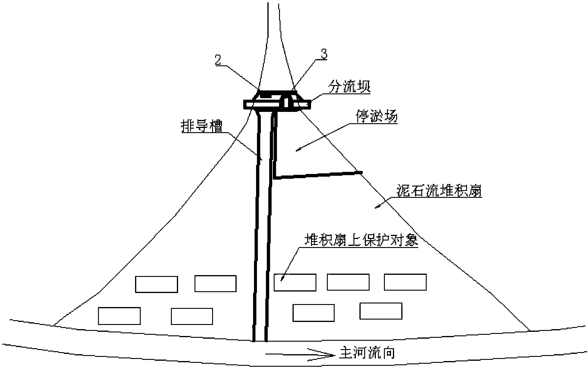
[0027] Such as figure 1 , figure 2 shown. The drainage area of ​​a debris flow ditch is 5.6km 2 , in order to control debris flow disasters, the prevention and control plan of building sand-blocking dams in the ditch, building a silt stop with accumulation fans, and a 4.0m bottom width row channel is adopted. For the 40m wide channel at the top of the accumulation fan, it is proposed to plan a diversion dam to distribute The amount of drainage and silting, the layout of the plane position is as follows: figure 2shown. The debris flow diversion dam that automatically distributes the amount of drainage and silting includes a dam body foundation 1 and a dam body body located on the dam body foundation 1; the bottom of the dam body body is provided with a diversion hole 2 connecting the row guide groove, The top of the main body of the dam body is provided with a diversion weir 3 connected to the silt stop; The cross-sectional size is determined according to the design flow...

Embodiment 2

[0033] Such as figure 1 , figure 2 shown. The same places as in Embodiment 1 will not be repeated, the difference is that the drainage area of ​​a certain debris flow ditch is 16.8km 2 , using the prevention and control plan of building a sand trap group in the ditch, building a silt stop with accumulation fans, and a 6.0m-bottom width row channel. The design flow rate Q of the guide groove drainage 84.0m 3 / s, the design flow Q of the parking lot deposit 62.0m 3 / s. The main body of the dam body is made of masonry material.

[0034] In the first step, the average width of the diversion weir 3 is preliminarily set b 2 is 5.0m, and the discharge coefficient m is taken as 0.46 according to the main material of the dam body, according to the formula h 2 = ( Q deposit m b ...


PUM


Abstract

Disclosed are a debris flow diversion dam automatically distributing drainage and silting and a design method thereof. The diversion dam comprises a dam foundation (1) and a dam main body provided on the dam foundation (1); the bottom part of the dam main body is provided with a diversion hole (2) connected to a drainage ditch, the top part of the dam main body is provided with a diversion weir (3) which is connected to a silting field; the diversion weir (3) is located above a side of the diversion hole (2), and the elevation of a top face of the diversion hole (2) is the same as the elevation of a bottom face of the diversion weir (3); and the size of the cross-sectional area of the diversion hole (2) is determined by the projected throughput of the drainage ditch, and the size of the cross-sectional area of the diversion weir (3) is determined by the projected throughput of the silting field. The debris flow diversion dam uses a diversion hole to control the throughput of debris flow entering the drainage ditch, rationally distributing the debris flow to the drainage ditch and the silting field, preventing a higher volume than the projected standard of debris flow from overflowing in the drainage ditch, and also preventing a higher volume than a projected standard of debris flow from entering a main river and creating a landslide dam.

Description

technical field [0001] The invention relates to a mud-rock flow prevention technology, in particular to a mud-rock flow diversion dam capable of automatically distributing a drainage volume and a silting volume and a design method thereof. Background technique [0002] Debris flow disaster is one of the main types of geological disasters in my country. On August 8, 2010, a large-scale debris flow broke out in Sanyanyu, Zhouqu County, Gansu Province. The debris flow silted up the county town and blocked the Bailong River to form a barrier lake that flooded nearly half of the county town, causing heavy casualties and property losses; on August 13, 2010 On the 1st, a large-scale mudslide broke out in Wenjiagou, Qingping Township, Mianzhu City, Sichuan Province, blocking the main river, causing more than ten people to die and disappear, and a large number of houses rebuilt after the Wenchuan Earthquake were buried. More and more attention has been paid to secondary disasters ca...

Claims


Application Information

Patent Timeline
Patent Type & Authority Patents(China)
IPC IPC(8): E02B7/02
CPCE02B8/023E02B3/02E02B7/04Y02A50/00
Inventor 陈晓清游勇崔鹏陈建刚李昆
Owner INST OF MOUNTAIN HAZARDS & ENVIRONMENT CHINESE ACADEMY OF SCI
Learn More