Magnetorheological buffering unit structure based on impact load and control method thereof

A shock load and buffer unit technology, applied in the field of shock load buffer devices, can solve the problems of non-adjustable parameters of the oil-air buffer, difficulty in taking into account sliding and landing of the landing gear buffer, and achieve optimal buffering effect and reasonable structure , Quick and effective adjustment effect

Inactive Publication Date: 2013-07-10
SHENYANG AEROSPACE UNIVERSITY
View PDF11 Cites 25 Cited by
  • Summary
  • Abstract
  • Description
  • Claims
  • Application Information

AI Technical Summary

Problems solved by technology

[0005] The purpose of the present invention is to solve the above-mentioned problems, and mainly solve the problem that the parameters of the oil-gas type buffer are not adjustable during the working

Method used


Image

  • Magnetorheological buffering unit structure based on impact load and control method thereof
  • Magnetorheological buffering unit structure based on impact load and control method thereof
  • Magnetorheological buffering unit structure based on impact load and control method thereof

Examples


Embodiment

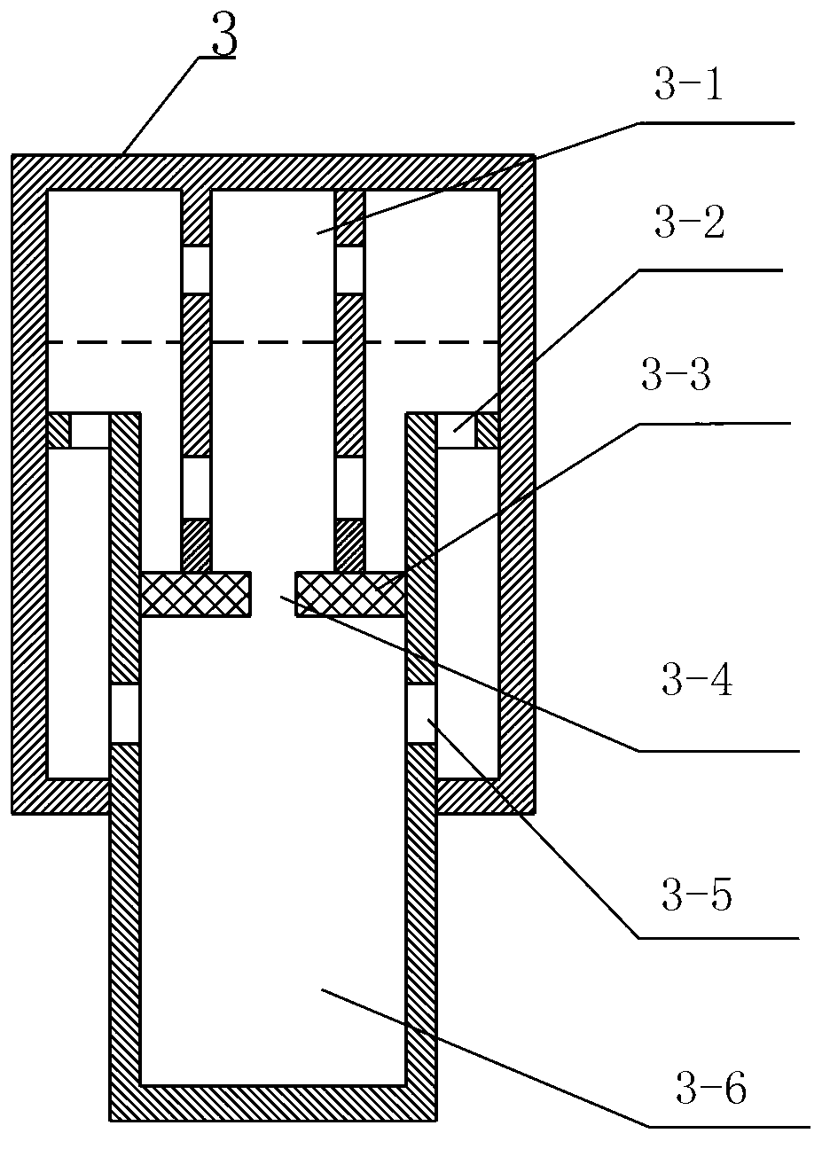
[0026] refer to figure 1 , a magnetorheological buffer unit structure facing impact loads, including a magnetorheological damper 3 and a magnetorheological fluid cavity 3-6, the magnetorheological damper 3 and the magnetorheological fluid cavity 3-6 are chambers body structure, wherein the magnetorheological fluid cavity 3-6 is set in the cavity of the magnetorheological damper 3, and the two wings of the upper end of the magnetorheological fluid cavity 3-6 are respectively provided with oil return holes 3-2; the two sides are respectively provided with side oil holes 3- 5. The magnetorheological fluid chamber 3-6 is provided with an excitation coil 3-3, and a main oil hole 3-4 is formed inside the excitation coil 3-3. The magnetorheological damper 3 is provided with an air chamber 3-1 and The cavities of the magnetorheological fluid chambers 3-6 communicate with each other, and the magnetorheological fluid chambers 3-6 move in the magnetorheological damper 3 through the seali...


PUM


Abstract

The invention discloses a magnetorheological buffering unit structure based on impact load and a control method thereof, aiming to mainly solve the technical problems that parameters of an oil-gas type buffer cannot be adjusted in working process, and accordingly a landing gear buffer cannot be balanced with a large power energy source required from outside for realizing ground sliding, landing off and actively controlling the landing gear. The magnetorheological buffering unit structure comprises a magnetorheological damper and a magnetorheological liquid chamber, and the magnetorheological liquid chamber can move in the magnetorheological damper through a sealing device. During testing, the unit structure main body is mounted on an impact test platform. Variable-structure oil holes of a conventional oil-gas type buffer are replaced by oil-needle-free constant-interface oil holes, passed oil damping force is controlled by applied magnetic field, and magnetic field is supplied by applied current. The magnetorheological buffering unit structure is reasonable in structure and capable of buffering impact energy produced by impact force effectively, and meanwhile, oil return holes can prevent wheels from jumping off the ground while landing. The magnetorheological buffering unit structure has functions of an oil-gas type passive-control buffer, realizes half-active buffer control effect, and is mainly applied to the technical field of aviation.

Description

technical field [0001] The invention relates to a magneto-rheological buffer unit structure facing impact loads, in particular to an impact load buffering device used in conjunction with aircraft landing gear. At the same time, aiming at the buffer control problem of the above-mentioned unit structure, a control strategy that effectively avoids the complex influence of the control method caused by the nonlinearity of the magnetorheological fluid is proposed, and the design and programming implementation of the control based on model prediction are completed. Mainly used in the field of aviation technology. Background technique [0002] Taking aircraft landing gear as an example, most aircraft landing gears at home and abroad currently use oil-pneumatic passive control buffers. The oil-pneumatic buffer has the advantages of simple structure, easy realization and high reliability. But once it is manufactured, its parameters cannot be adjusted during the working process, and ...

Claims


Application Information

Patent Timeline
IPC IPC(8): F16F9/53G01M7/08G05B13/02
Inventor 傅莉关威王琦胡为
Owner SHENYANG AEROSPACE UNIVERSITY
Why Eureka
Try Eureka