General testing system of airplane direct-current generator

A DC generator and general testing technology, applied in the field of test systems, can solve the problems of inconvenient testing of aircraft DC generators, complicated expansion and modification of test software, lack of versatility, etc., to facilitate manual monitoring, function upgrade and expansion, The effect of broadening applicability

Inactive Publication Date: 2013-07-10
GUANGZHOU AIRCRAFT MAINTENANCE ENG
7 Cites 8 Cited by

AI-Extracted Technical Summary

Problems solved by technology

However, the current test system has a single function. As the market or generator equipment test requirements change, the hardware configuration of the aircraft DC generator and...

Method used

The control system of control system control system sampling Avtron company, comprises main controller and auxiliary controller, and main controller connects respectively and connects synchronous motor, motor dragging system, load system respectively, and measures and obtains synchronous motor, motor dragging respectively The parameter data of the dynamic system and the load system; the auxiliary controller is connected with the DC generator of the tested aircraft, an...

Abstract

The invention discloses a general testing system of an airplane direct-current generator. The general testing system of the airplane direct-current generator comprises a synchronous motor, a motor dragging system, a load system, and a control system, wherein the synchronous motor is used for driving a tested airplane direct-current generator, the motor dragging system is used for controlling the synchronous motor in a speed-control mode, the load system is used for providing load for the tested airplane direct-current generator, and the control system is used for controlling testing conditions of the tested airplane direct-current generator and detecting a test result of the tested airplane direct-current generator. The control system is respectively connected with the synchronous motor, the motor dragging system, the load system and the tested airplane direct-current generator. The load system is connected with the tested airplane direct-current generator. The motor dragging system is connected with the synchronous motor. The tested airplane direct-current generator is installed on the synchronous motor. The general testing system of the airplane direct-current generator can achieve a general test of various airplane direct-current generators.

Application Domain

Dynamo-electric machine testing

Technology Topic

Synchronous motorAirplane +7

Image

  • General testing system of airplane direct-current generator
  • General testing system of airplane direct-current generator

Examples

  • Experimental program(1)

Example Embodiment

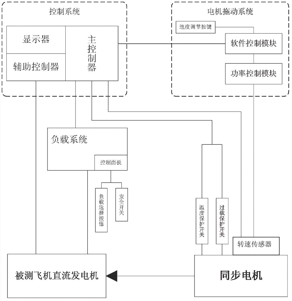
[0029] Such as figure 1 The general test system of the aircraft DC generator shown in the general test system includes: a synchronous motor used to drive the DC generator of the aircraft under test, a motor drive system used for speed regulation and control of the synchronous motor, and a test aircraft The DC generator provides a load load system and a control system for controlling the test conditions of the tested aircraft DC generator and detecting the test results of the tested aircraft DC generator.
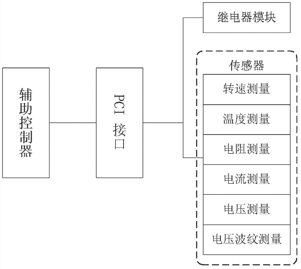
[0030] The control system control system samples Avtron’s control system, including the main controller and the auxiliary controller. The main controller is connected to the synchronous motor, the motor drive system, and the load system. The synchronous motor, motor drive system, The parameter data of the load system; the auxiliary controller is connected to the DC generator of the aircraft under test and measures the parameter data of the aircraft DC generator. The control system of this embodiment adopts NI (National Instruments) LabVIEW secondary development software system, cooperates with the interface display module (ie display) and data processing module, real-time display test status and test parameters, assist in troubleshooting, compact structure, and performance Stable and reliable.
[0031] The DC generator of the tested aircraft is installed on a synchronous motor, and the DC generator of the tested aircraft is driven to rotate by the synchronous motor to generate electricity. The synchronous motor is provided with a speed sensor, which is respectively connected with the main controller and the power control module, and the speed data of the synchronous motor can be transmitted to the main controller and the power control module, and is controlled by the power control module and the main controller. The synchronous motor is also equipped with an overload protection switch for synchronous motor overload protection and a temperature protection switch for synchronous motor overtemperature protection. The overload protection switch and temperature protection switch are respectively connected to the main controller, and the controller detects the synchronous motor overload Or when the temperature is over, the power of the synchronous motor is automatically cut off to realize protection. Among them, the test bench facilitates stable testing of the DUT by using general electric connectors and installation fixtures. For DUTs of different shapes, only corresponding fixtures and adapters need to be adapted accordingly.
[0032] In this embodiment, the synchronous motor is stably fixed on the test bench, and a synchronous motor of model 1FE1 is selected, which can provide a maximum torque of 26.5Nm, a maximum speed of 15000rpm, a rated speed of 7500rpm, and a rated power of 21kW. The maximum speed can be reached when loaded, and it is suitable for high-speed, low-torque load drive load testing, including low-speed drive, over-speed and rated speed tests.
[0033] Such as figure 2 As shown, the DC generator of the aircraft under test is equipped with sensors for temperature, speed, voltage, current, bearing resistance and voltage ripple measurement of the DC generator of the aircraft under test, and relays for controlling the action of the DC generator of the aircraft under test. The module and the auxiliary controller have a one-to-one correspondence with the PCI interface of each sensor, and use the PCI bus for connection and communication. Among them, the sensor specifically adopts thermocouple modules, rotational speed sensors, multimeter cards and oscilloscopes and other corresponding measurement function devices, which can collect the working parameters and communication data of the tested part, and respectively realize the rotational speed and temperature measurement of the DC generator of the tested aircraft. , Resistance measurement, current measurement, voltage measurement and voltage ripple measurement.
[0034] The motor drive system adopts Siemens' motor drive system, which includes a power control module, a software control module and a speed adjustment button. The power control module is connected to the synchronous motor and the software control module respectively, and the software control module is connected to the main controller. The software controls The module is connected with a speed adjustment button; the power control module automatically adjusts the speed of the synchronous motor through the software control module and according to the control signal of the control system, and can also manually control the synchronous motor for speed adjustment through the speed adjustment button. For different tested aircraft DC generators, different test parameters can be set in the main controller, and different speed control programs can be programmed in the software control module to achieve an adaptive simulation test environment. The motor drive system is a closed-loop control system, which adjusts and controls the rotation speed of the synchronous motor according to the control signal command signal of the control system, and the manual and automatic speed control of the synchronous motor is realized through the power control module. The motor drive system is easy to operate, and the components can be tested manually or fully automatically tested through the written program.
[0035] The load system has a load box and a control panel, and uses the load system of Avtron. The control panel is mainly used for manual control. Both automatic control and manual control realize different load requirements by operating the relevant relays of the load box. The load box can provide 5, 10, 10, 25, 50, 100, 100, 200 and 500 amperes and a total load of 1000 amperes at 28 volts DC. The maximum safe working voltage of the load box is 31 DC volts. The load box has a resolution of 5 amperes, which is suitable for testing various DC generators. The load box is equipped with a door protection switch, which is in a protected state when the door is opened and cannot be powered on to ensure safety during shutdown and maintenance. The control panel is equipped with a load control button for manually adjusting the load capacity and a safety switch for manually disconnecting the power supply of the load system for manual manual load adjustment and manual manual unloading.
[0036] The control system is equipped with a display used to display the measured parameter data. The auxiliary controller measures the various functional parameters on the tested aircraft DC generator, and the main controller measures each data parameter to be displayed on the display. It is used for manual monitoring of data parameters displayed on the display on the basis of automatic control, and then manual operation by manual switches for auxiliary or backup control testing.
[0037] The working principle of this system:
[0038] By setting test parameters for the main controller and software control module, the main controller is compared with the set test parameters with the parameter data measured by the main controller from the synchronous motor, the motor drive system, the load system, and the DC generator of the tested aircraft , The main controller sends a control signal to control the motor drive system to adjust the speed of the synchronous motor, and the main controller sends a control signal to control and adjust the load capacity of the load system to complete the simulated environment of the tested aircraft DC generator. The functional parameters during the test of the aircraft DC generator are measured by the auxiliary controller, and these functional parameters are processed in the main controller to obtain the test results. Specifically: the main controller connects the synchronous motor to start and adjust the speed through the control bus, controls the adjustment of the load box capacity and reads the test data, and at the same time adjusts the speed of the synchronous motor through the power control module through the control bus and reads the loading data at the same time. Load the load box and display the synchronous motor speed control parameter data on the same test interface on the display; the auxiliary console is connected to the DC generator of the tested aircraft through the PCI interface card of NI (National Instruments), and collects the data of the tested part. Working parameters and test data such as voltage, current and resistance.
[0039] The embodiments of the present invention are not limited to this. According to the above content of the present invention, using common technical knowledge and conventional means in the field, the present invention can also be made in various other forms without departing from the above basic technical ideas of the present invention. Modifications, replacements or alterations fall within the protection scope of the present invention.

PUM

no PUM

Description & Claims & Application Information

We can also present the details of the Description, Claims and Application information to help users get a comprehensive understanding of the technical details of the patent, such as background art, summary of invention, brief description of drawings, description of embodiments, and other original content. On the other hand, users can also determine the specific scope of protection of the technology through the list of claims; as well as understand the changes in the life cycle of the technology with the presentation of the patent timeline. Login to view more.

Similar technology patents

Creasing equipment for carton production

Owner:郴州新骏纸品包装有限公司

Classification and recommendation of technical efficacy words

  • Improve applicability
Why Eureka
Try Eureka