Intelligent fault report optical transceiver and network management client system thereof

A technology of optical transceivers and optical terminals, applied in transmission systems, closed-circuit television systems, televisions, etc., can solve problems such as imperfect address configuration of Internet of Things devices, power failure of optical transceiver equipment and failure of optical fiber judgment, and inability to control equipment, etc.

Inactive Publication Date: 2013-07-10
广州澳视互动传媒有限公司
View PDF4 Cites 9 Cited by
  • Summary
  • Abstract
  • Description
  • Claims
  • Application Information

AI Technical Summary

Problems solved by technology

[0005] 1. It can only monitor the running status of the equipment, but cannot control the equipment;
[0006] 2. It can only monitor the running status of its own equipment, and cannot manage the connected high-speed ball, camera and other equipment or can only provide data channels for the connected equipment to manage and transmit data;
[0007] 3. There is no or very low accuracy in judging the power failure of the optical transceiver equipment and the disconnection of the optical fiber;
[0008] 4. The configuration of the Internet of Things device address is not perfect, mainly through manual configuration

Method used


Image

  • Intelligent fault report optical transceiver and network management client system thereof
  • Intelligent fault report optical transceiver and network management client system thereof
  • Intelligent fault report optical transceiver and network management client system thereof

Examples


Embodiment Construction

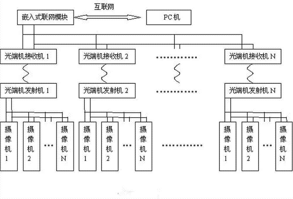
[0068] as attached Figures 1 to 9 As shown in any figure, a smart alarm alarm optical transceiver, which includes the optical transceiver body, is characterized in that it includes:

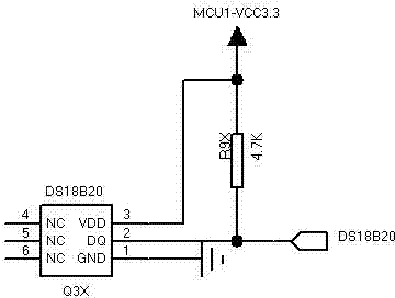
[0069] The optical transceiver body is equipped with a DS18B20 temperature acquisition chip. The temperature acquisition chip stores the temperature data collected in real time in the internal register, and when the controller needs data, it reads the binary data from the register, and then converts the binary data to Decimal temperature data;

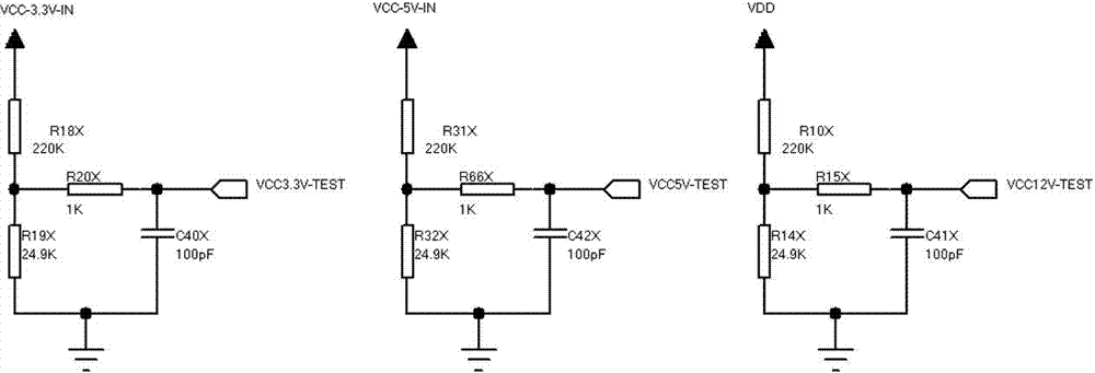
[0070] The optical transceiver body is provided with a voltage detection circuit, and the voltage detection circuit is sent to the I / O port of the single-chip microcomputer through resistance voltage division sampling, and then the actual voltage is calculated by the A / D circuit inside the single-chip microcomputer, and then uploaded to the platform software;

[0071] There is a remote switch control circuit in the optical transceiver body. This system ...


PUM


Abstract

The invention relates to an intelligent fault report optical transceiver and a network management client system thereof and particularly provides a thorough solution for working-state 24-hour real-time monitoring and fault process of an optical transceiver in a traditional video system. A temperature detecting circuit, a voltage detecting circuit, a remote switching-on and switching-off reset circuit and a STC12LE5A08S2 serving as a main control MCU are arranged inside the optical transceiver. The system of the intelligent fault report optical transceiver is composed of an allocation model of the internet of things, achievement of a high-speed ball control signal (PZE) and a web master signals multiple connection, and a data collection item. The state of the optical transceiver, and operation states of a high-speed ball and a camera which are downwards connected are transmitted to a management center in real time, remote switching-on, remote switching-off and remote reset of all optical transceivers and downwards connected equipment can be conducted, and accurate judgment can be conduct on power failure of the optical transceiver and broken optical fiber states.

Description

Technical field: [0001] The invention relates to an optical transceiver and its management system, specifically providing a perfect solution for the 24-hour real-time monitoring of the working status of the optical transceiver in the traditional video system and troubleshooting. Background technique: [0002] Entering the 21st century, the global anti-terrorism and security situation is becoming more and more severe, and the role of video surveillance systems is prominent, with tens of thousands of cameras all over every corner of the city. [0003] As we all know, due to factors such as lightning strikes, power supply failures, and man-made sabotage, once the optical transceiver used as the transmission is abnormal, the monitoring of the relevant area is useless. Even if it is a small monitoring system, the abnormality of this kind of equipment may cause very serious consequences. However, this kind of abnormality is often not easy to be discovered by the on-duty perso...

Claims


Application Information

Patent Timeline
Patent Type & Authority Applications(China)
IPC IPC(8): H04N7/18H04N17/00H04B10/40H04L29/12
Inventor 周维林于辉
Owner 广州澳视互动传媒有限公司
Why Eureka
Try Eureka