Pot heat exchanger

A heat exchanger and gas purification technology, applied in heat exchange equipment, heat exchangers, indirect heat exchangers, etc., to achieve uniform or balanced unpurified gas velocity, low total system energy loss, and less energy

Active Publication Date: 2013-07-10
GENERAL ELECTRIC TECH GMBH
View PDF7 Cites 3 Cited by
  • Summary
  • Abstract
  • Description
  • Claims
  • Application Information

AI Technical Summary

Problems solved by technology

This occurs because raw gas collection piping and gas cleaning units can

Method used


Image

  • Pot heat exchanger
  • Pot heat exchanger
  • Pot heat exchanger

Examples


Embodiment Construction

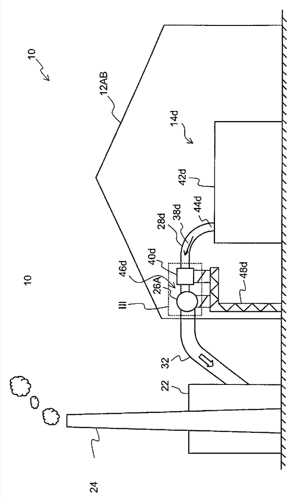
[0026] FIG. 1 is a schematic view of an aluminum manufacturing plant 10 viewed from above. Aluminum fabrication plant 10 includes a plurality of pot rooms 12 or pothouses 12AB, 12CD, each pot room 12 including a plurality of aluminum production melting pots or pots 14 . The electrolysis cells 14 are arranged in a series of electrolysis cells in a manner well known to those skilled in the art. The series of electrolysers comprises a plurality of electrolysers connected in series in a direct current (DC) loop. Figure 1 shows a first electrolysis cell bay 12AB and a second electrolysis cell bay 12CD, each housing a respective series of electrolysis cells 16AB, 16CD. Although a single pot series 16AB, 16CD in FIG. 1 is shown housed in a single pot bay 12AB, 12CD, a single pot series 16 defined as a plurality of melting pots electrically connected in series may also span only several pots. The bay 12 extends. For example, as an alternative to the configuration described above, t...


PUM


Abstract

A raw gas collection system for collecting raw gas from a plurality of aluminium smelting pots is equipped with a plurality of branch ducts (28d), each of which is arranged to channel a respective branch flow (38d) of raw gas from an aluminium smelting pot to a collection duct (26A), which is common to and shared by the branch ducts (28d). Each of said branch ducts (28d) is, near an outlet (52d) thereof, equipped with a curved section (50d) for aligning the branch flow (38d) with a flow direction of raw gas (27A) already present in the common collection duct (26A), and a constriction (54d) for accelerating the branch flow (38d) through the branch duct outlet (52d) into the common collection duct (26A). Furthermore, each of said branch ducts (28d) is equipped with a heat exchanger (40d) for removing heat from the respective branch flow (38d) of raw gas.; The combined flow resistance of the constriction (54d) and the heat exchanger (40d) reduces the need for adjusting the respective branch flows (28d) using dampers, thereby reducing the power required to transport the raw gas.

Description

technical field [0001] The present invention relates to a raw gas collection system for collecting raw gas from a plurality of aluminum smelting pots. The invention also relates to a method of moving a side stream of raw gas from an aluminum smelting pot to a common collection pipe. Background technique [0002] Aluminum is typically produced by electrolysis using one or more aluminum production cells. Such electrolytic cells typically include a bath for containing bath contents containing fluoride-containing minerals on top of molten aluminium. The bath contents are in contact with the cathode block and the anode block. Aluminum oxide was supplied to the bath at regular intervals via openings at several locations along the center of the tank and between the rows of anodes. [0003] The electrolysis reaction that occurs in the electrolysis cell generates hot exhaust gases that include gaseous components that are undesirable in the atmosphere, including hydrogen fluoride, ...

Claims


Application Information

Patent Timeline
IPC IPC(8): C25C3/22F17D1/04F27D1/00
CPCF27B14/08F27D17/001F27D17/004F28D7/1615F28D7/1653F28D21/0003F28F9/0282F28F13/08F28F19/00C25C3/22Y10T137/6416C25C7/06C25C3/06C25C3/24F27D17/002Y02P10/25
Inventor A.K.索尔胡斯G.维德O.E.比亚尔诺
Owner GENERAL ELECTRIC TECH GMBH
Why Eureka
Try Eureka