

Magnetic resonance imaging apparatus
A technology of magnetic resonance imaging and gradient magnetic field, which is applied in measuring devices, measuring magnetic variables, medical science, etc., can solve problems such as image quality degradation, and achieve the effect of suppressing image quality degradation
- Summary
- Abstract
- Description
- Claims
- Application Information
AI Technical Summary
Problems solved by technology
Method used
Image

Examples
no. 1 Embodiment approach )
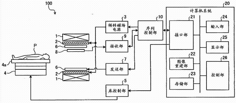
[0020] figure 1 It is a diagram showing the configuration of the MRI apparatus according to the first embodiment. Such as figure 1 As shown, the MRI apparatus 100 includes: a static magnetic field magnet 1, a gradient magnetic field coil (coil) 2, a gradient magnetic field power supply 3, a bed 4, a bed control unit 5, a transmitting RF coil 6, a transmitting unit 7, a receiving RF coil 8, a receiving Part 9, sequence control part 10 and computer system (system) 20.
[0021] The static field magnet 1 is a hollow cylindrical magnet, and generates a uniform static magnetic field in the internal space. As the static field magnet 1, for example, a permanent magnet, a superconducting magnet, or the like is used.
[0022] The gradient coil 2 is a hollow cylindrical coil and is arranged inside the static field magnet 1 . This gradient magnetic field coil 2 is formed by combining three coils corresponding to the mutually orthogonal X, Y, and Z axes. These three coils are individua...
no. 2 Embodiment approach )
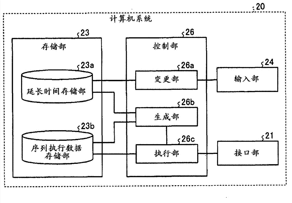
[0074] In addition, in the above-mentioned embodiment, an example was described in which the slice selection in each refocusing pulse was deselected in the pulse sequence of the FSE method, but the embodiment is not limited thereto. For example, the techniques described in the above embodiments can be similarly implemented when performing slice selection in each refocusing pulse in the pulse sequence of the FSE method. Hereinafter, an example at this time will be described as a second embodiment. In addition, the MRI apparatus according to the second embodiment is basically the same as figure 1 The devices shown in and 3 are the same, but the pulse sequence generated by the generating unit 26b is different.
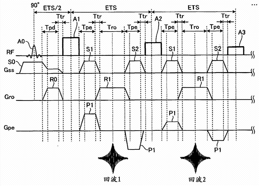
[0075] Figure 10 It is a figure which shows an example of the pulse sequence of the FSE method concerning 2nd Embodiment. here, Figure 10 The example shown is with figure 2 The pulse sequence when using the VFA method is the same, but the point for slice selection...
no. 3 Embodiment approach )
[0083] In addition, in the above-mentioned embodiment, an example of imaging by the FSE method has been described, but the embodiment is not limited thereto. For example, the techniques described in the above embodiments can be similarly implemented when performing imaging by the spin echo (Spin Echo: SE) method. Hereinafter, an example at this time will be described as a third embodiment. In addition, the MRI apparatus according to the third embodiment is basically the same as figure 1 The devices shown in and 3 are the same, but the pulse sequence generated by the generating unit 26b is different.
[0084] Figure 11 It is a diagram showing an example of a pulse sequence of the SE method according to the third embodiment. Such as Figure 11 As shown, in the SE method, the refocusing pulse A1 is applied after TE (Echo Time) / 2 has elapsed since the excitation pulse A0 (90° pulse) was applied. Accordingly, after TE has elapsed since the application of the excitation pulse ...
PUM
 Abstract
Description
Claims
Application Information