Equipment and method for improving sand lined casting efficiency

A sand-covered molding and high-efficiency technology, which is applied in the field of iron mold sand-coated casting, can solve the problems of no substantial improvement in molding efficiency, no mold cleaning, etc., and achieve the effect of facilitating layout, convenient manual operation, and convenient mold change

Active Publication Date: 2013-07-17
浙江省机电设计研究院有限公司
View PDF7 Cites 14 Cited by
  • Summary
  • Abstract
  • Description
  • Claims
  • Application Information

AI Technical Summary

Problems solved by technology

[0006] Chinese Patent No. 201220113604.3 discloses a utility model patent named "a sand-covered molding machine", which includes a frame, the frame includes a top box and a column connected to the bottom of the top box, and the bottom of the top box is set There is a sand-covered cover, and a support roller table is set under the sand-covered cover. The support pipe extends to both sides to form a conveying roller table section, and a stopper is arranged on the support roller table. Although the structure of this patent is simple, there is no mold cleaning, etc. structure, so there are still the above defects
[0007] China Patent No. 200820085552.7 discloses a utility model patent named "Sand-coated molding machine adapted to automatic production line". This patent moves in and out by rails, and moves the sand-coated iron mold from directly above the mold to the outside of the mold. Clearing up a certain space for mold cleaning facilitates the cleaning work to a certain extent, but for the entire sand-covered molding process, the five processes are still concentrated in the same station, which has no substantial impact on the molding efficiency. improved, so there are still the above defects

Method used


Image

  • Equipment and method for improving sand lined casting efficiency
  • Equipment and method for improving sand lined casting efficiency
  • Equipment and method for improving sand lined casting efficiency

Examples


Embodiment Construction

[0030] The present invention will be further described below in conjunction with the accompanying drawings and embodiments.

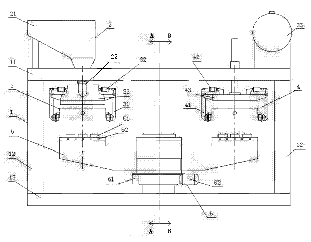
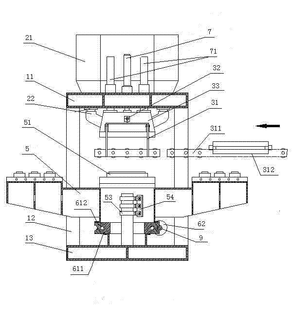
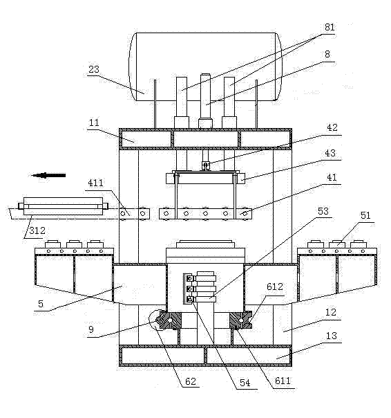
[0031] see Figure 1 to Figure 6, This embodiment includes a support frame 1, a sanding and sand shooting device 2, a lifting sand shooting head 3, a lifting roller table opening and closing mechanism 4, a four-station workbench 5 and a rotating mechanism 6.

[0032] The support frame 1 comprises an upper beam 11, a column 12 and a base 13, the column 12 is connected between the upper beam 11 and the base 13, and the three are fixed as a whole, and one side of the upper beam 11 is connected with a lifting type sand shooting head 3, and the other The side is connected with a lifting type roller table opening and closing mechanism 4, and a rotating mechanism 6 is installed on the base 13, and a four-station workbench 5 is fixed on the rotating mechanism 6.

[0033] Sand-adding and sand-shooting device 2 includes a sand-adding bucket 21, an automatic sand...


PUM


Abstract

The invention relates to equipment and a method for improving sand lined casting efficiency, and belongs to the technical field of iron sand lined casting. The equipment comprises a supporting frame composed of an upper beam, a base and a vertical pillar between the upper beam and the base, a sand adding and jetting device, and a rotating mechanism arranged on the base. The equipment is characterized by further comprising a four-station working platform, a lifting type sand jetting head and a lifting type roller bed opening and closing mechanism, wherein the four-station working platform is fixed on the rotating mechanism; the lifting type sand jetting head is connected at one side of the upper beam, and the lifting type roller bed opening and closing mechanism is connected at the other side; the lifting type sand jetting head and the lifting type roller bed opening and closing mechanism are respectively arranged on left and right sides; and the four-station working platform is arranged below the lifting type sand jetting head and the lifting type roller bed opening and closing mechanism. The equipment disclosed by the invention is reasonable in structure and design, convenient to clean mold, high in sand lined casting efficiency and convenient for users to operate.

Description

technical field [0001] The invention relates to a casting device and method, in particular to a device and a method for improving sand-covered molding efficiency, belonging to the technical field of iron mold sand-covered casting. Background technique [0002] Sand-coated iron mold is a special casting process that blows coated sand into the gap between the mold heated to a certain temperature and the iron mold, and hardens it into shape. With the advantages of its own technology, and with the development of the automobile industry and With the rise of the cement industry, the application range of sand-coated iron molds has become wider and wider, especially suitable for the mass production of small and medium-sized castings, so the sand-coated iron mold production line has been widely promoted. [0003] As the core equipment of the production line--sand-covered molding machine, its molding efficiency is the main factor determining the speed of the production line. There are...

Claims


Application Information

Patent Timeline
Patent Type & Authority Applications(China)
IPC IPC(8): B22C15/24
Inventor 刘同帮黄列群沈永华潘东杰夏小江洪华泽费巍峻
Owner 浙江省机电设计研究院有限公司
Why Eureka
Try Eureka