Lathing device for iron core of efficient motor without end plate at two ends and machining method thereof

A technology of turning processing and endless plate, applied in metal processing equipment, turning equipment, turning equipment, etc., can solve the problems of affecting the appearance quality, unable to achieve aesthetic effects, wasting labor hours, etc., to avoid processing risks, product beauty, and saving The effect of production costs

Active Publication Date: 2013-07-17
NANTONG TONGDA SILICON STEEL STAMPING TECH CO LTD
View PDF0 Cites 5 Cited by
  • Summary
  • Abstract
  • Description
  • Claims
  • Application Information

AI Technical Summary

Problems solved by technology

This not only wastes a lot of man-hours, but once deformed, no matter how it is repaired, the original aesthetic effect cannot be achieved. The iron core is formed by pressure on a press, which affects the appearance quality, such as figure 2 Shown is a schematic diagram of lathe processing according to the traditional craft

Method used


Image

  • Lathing device for iron core of efficient motor without end plate at two ends and machining method thereof
  • Lathing device for iron core of efficient motor without end plate at two ends and machining method thereof
  • Lathing device for iron core of efficient motor without end plate at two ends and machining method thereof

Examples


Embodiment Construction

[0022] The accompanying drawings non-limitatively disclose a high-efficiency motor core turning method without end plates at both ends involved in the present invention. The technical processing scheme of the present invention will be described in detail below in conjunction with the accompanying drawings.

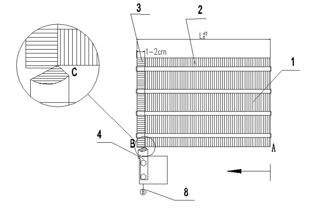
[0023] figure 1 It shows the running route of the turning tool, that is, the tool moves from the A end until the point C is 1-2cm away from the B end of the other end of the iron core. The scale size on the dial indicator 9 coincides with the beginning of the cutting tool, and it is only necessary to go in the opposite direction until it coincides with the forward turning process.

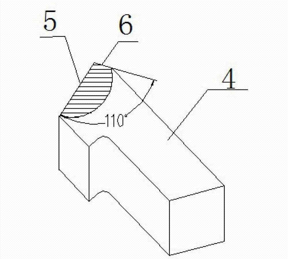
[0024] image 3 It is a schematic diagram of the structure of the turning tool. Make sure there are two cutting edges, that is, the first cutting edge and the second cutting edge. The faster the grinding, the better the turning effect. The angle between the two cutting edges is about 110o . ...


PUM

PropertyMeasurementUnit
angleaaaaaaaaaa
angleaaaaaaaaaa

Abstract

The invention discloses a lathing device for an iron core of an efficient motor without an end plate at two ends and a machining method thereof. The lathing device comprises a lathe, two thimbles and a clamping fixture, wherein the thimbles clamp the iron core of the motor through the clamping fixture; correspondingly, the iron core of the motor is provided with a knife rest; the knife rest is provided with a lathe tool which includes a first cutting edge and a second cutting edge; the included angle between the two cutting edges is 100-115 degrees; and the machining steps are as follows: step A, machining by using the first cutting edge, and when the knife is moved from an A end face to have a distance of 1-2 cm to a B end face, retracting the knife to a B end; step B, machining by using the second cutting edge, and when the knife is moved from the B end to have a distance of 1-2 cm to the A end face, retracting the knife to an A end; and carrying out the Step A and the Step B alternately until a set qualified size is obtained. The machining process improves production efficiency, increases product quality, avoids machining risk, realizes requirements on aesthetic sense and high precision of products, saves production cost and increases production benefits as repeated manual subsequent arrangement is unnecessary and the lathe tool is not easy to damage.

Description

technical field [0001] The invention relates to a high-efficiency motor core-turning device without end plates at both ends and a processing method thereof, which is especially suitable for high-efficiency energy-saving motor core turning without end plates at both ends, and belongs to the field of motor and generator manufacturing. Background technique [0002] At present, when high-end customers at home and abroad are designing motors, especially high-efficiency motors and low-voltage high-power motors, considering the performance of the entire motor, they do not use end plates (1~2mm steel plates) to press on both ends, but at the end of the processing of the iron core When turning a process, the turning process is carried out according to the normal processing technology, that is, the rough and finishing machining is directly performed with the turning tool, which will cause the spring-opening of the iron core to increase significantly, especially where there is no buckle...

Claims


Application Information

Patent Timeline
Patent Type & Authority Applications(China)
IPC IPC(8): B23B5/00B23B1/00H02K15/02
CPCH02K15/02
Inventor 宋建强钱斌
Owner NANTONG TONGDA SILICON STEEL STAMPING TECH CO LTD
Why Eureka
Try Eureka