
Damping structure for knapsack equipment

A knapsack and equipment technology, applied in the field of mechanical design and manufacturing, mechanical shock absorption design and manufacturing, can solve the problems of unstable rotation speed, large mechanical vibration, unstable load, etc., to achieve good structure matching, reduced vibration transmission, and shock absorption structure. concise effect

Inactive Publication Date: 2013-07-17
DONGGUAN SIHUIWEI ELECTRONICS TECH CO LTD
View PDF7 Cites 3 Cited by
  • Summary
  • Abstract
  • Description
  • Claims
  • Application Information

AI Technical Summary

Problems solved by technology

In order to facilitate the water spray under the moving state, the existing small water spray portable devices usually have their own power device, and the power device mostly uses a gasoline engine, etc. During the working process of the engine, the load is not stable, the speed is unstable, and the mechanical vibration is very large. The staff on the back have a greater sense of discomfort, do not use their health to work, and at the same time cause damage to the equipment itself
[0003] Usually, considering the miniaturization requirements of water spray portable devices, the structural method of adding elastic material cushioning at the fixed connection between the vibration equipment and the fixing parts is adopted, such as adding rubber pads to the connecting bolts, and adding buffer rubber to the fixed base of the vibration equipment. and other structural methods, although the above-mentioned structural method partially buffers the vibration transmission, it does not consider the shock absorption from the overall equipment, and cannot meet the further comfort and safety requirements for the backpack-type small water spray portable device.

Method used


Image

  • Damping structure for knapsack equipment
  • Damping structure for knapsack equipment
  • Damping structure for knapsack equipment

Examples


Embodiment Construction

[0028] The present invention is further described by the following examples. This example is only used to further illustrate the present invention, but it cannot be interpreted as limiting the protection scope of the present invention. Essential improvements and adjustments belong to the protection scope of the present invention.

[0029] combine Figure 1 to Figure 7 .

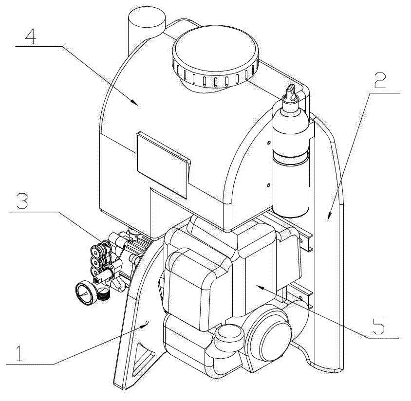
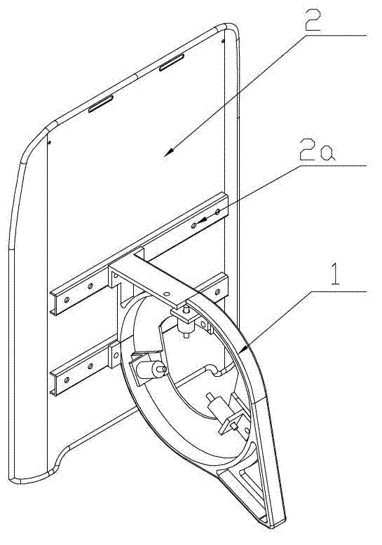
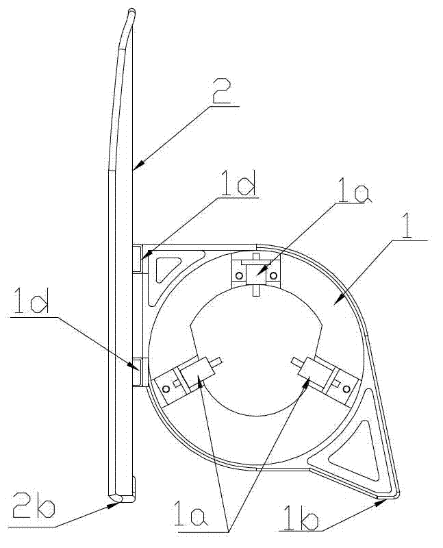
[0030] As shown in the figure, the shock absorbing structure of the knapsack equipment includes a back frame 2 for people to carry, a water tank 4 installed on the back frame 2, a motor pump 3 and an engine 5, the back frame 2 is a plate structure, and a bracket 1 The plane of the plate structure of the back frame 2 is vertically connected and fixed; the motor pump 3 and the motor 5 are connected to each other and fixed by elastic material 7 and the bracket 1. The motor pump 3 and the motor 5 are respectively located on both sides of the bracket 1.

[0031] There is a suspension hole in the middle of the su...


PUM


Abstract

The invention discloses a damping structure for knapsack equipment. The damping structure comprises a back frame used for backpacking of people, a water tank loaded and mounted on the back frame, a motor pump and an engine. The back frame is of board structure, and a support is perpendicularly fixedly connected with a plane of the board structure of the back frame in the vertical direction. The motor pump and the engine are flexibly suspended and fixed with the support through elastic materials after being in shaft connection with each other and are respectively arranged on two sides of the support. By adopting the open back frame and the perpendicularly mounted support structure, damping units are balanced and suspended on two sides of the support, and vibration transmission of the equipment is reduced to the greatest extent by a plurality of flexible suspending structures. The damping structure is integrally simple in structure and more accordant with requirements of human comfort, and is better in damping since all structures are matched better.

Description

technical field [0001] The invention belongs to the technical field of mechanical design and manufacture, in particular to the technical field of mechanical shock absorbing design and manufacture, and particularly relates to a shock absorbing structure of a backpack device. Background technique [0002] When fire extinguishing and agricultural water spraying, it is often applied to a small portable water spraying device. The existing portable device often adopts a backpack type, that is, the water spraying device including the water tank is carried on the back of the relevant personnel, and moves with the person to realize fire extinguishing, Spray water or spray pesticides. In order to facilitate the water spray under the moving state, the existing small water spray portable device usually has its own power device, and the power device mostly adopts a gasoline engine, etc. During the working process of the engine, the load is not stable, the speed is unstable, and the mecha...

Claims


Application Information

Patent Timeline
Patent Type & Authority Applications(China)
IPC IPC(8): F16M13/04F16F15/04F16F15/08
Inventor 王靖
Owner DONGGUAN SIHUIWEI ELECTRONICS TECH CO LTD
Learn More