Two-waveband common-path and common-focal-plane imaging system

An imaging system and common optical path technology, applied in the field of optics, can solve the problems of difficult suppression of stray light and low transmittance of the system, and achieve the effects of reduced volume, easy correction of chromatic aberration, and easy suppression

Active Publication Date: 2013-07-17
CHANNGCHUN CHANGGUANG ADVANCED OPTICS TECH CO LTD
View PDF5 Cites 26 Cited by
  • Summary
  • Abstract
  • Description
  • Claims
  • Application Information

AI Technical Summary

Problems solved by technology

[0007] The purpose of the present invention is to solve the problems of low system transmittance and difficulty in suppressing system stray light existing in ...

Method used


Image

  • Two-waveband common-path and common-focal-plane imaging system
  • Two-waveband common-path and common-focal-plane imaging system
  • Two-waveband common-path and common-focal-plane imaging system

Examples


Embodiment Construction

[0024] The present invention will be described in further detail below in conjunction with the accompanying drawings.

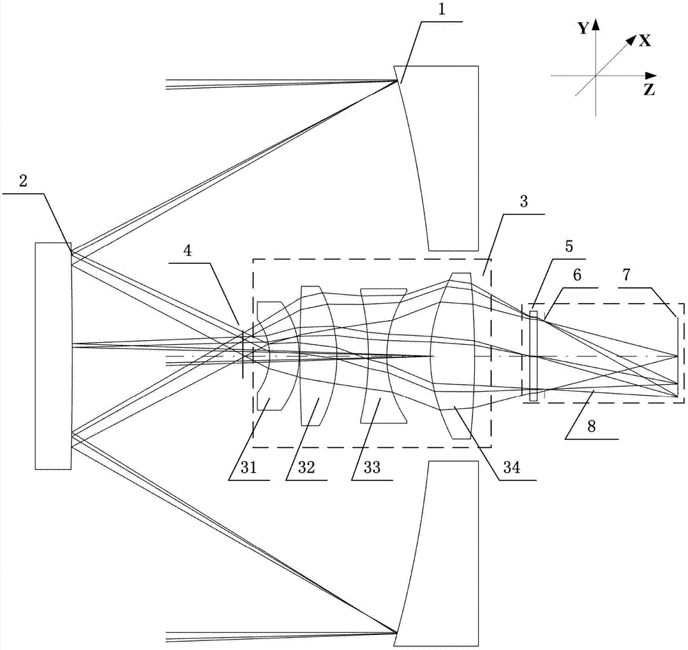
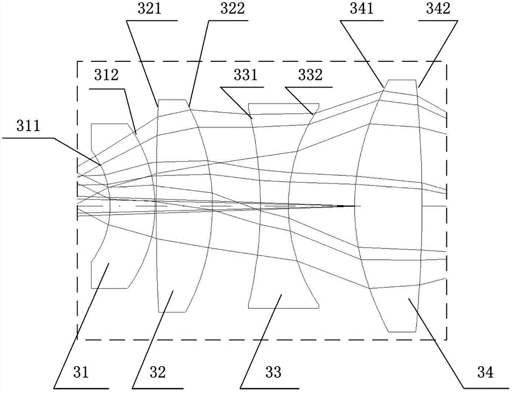
[0025] See attached figure 1 , 2 , the dual-band common optical path confocal surface imaging system of the present invention consists of a primary mirror 1, a secondary mirror 2, a relay mirror group 3 and a focal plane detector 8 in sequence from the object side to the image side. The focal plane detector 8 is a mid-wave infrared / long-wave infrared dual-band focal plane array 7 or a broadband focal plane array 7, which is used for imaging thermal radiation of 3 μm to 5 μm and 8 μm to 10 μm in the electromagnetic spectrum. Simultaneous long-wave infrared imaging.

[0026] The optical system of the present invention is arranged in an orderly manner according to the xyz right-handed space coordinate system, the z-axis direction is defined as the optical axis direction, and the y-axis is at figure 1 In the plane shown, the x-axis is perpendicular to the yz p...


PUM


Abstract

The invention discloses a two-waveband common-path and common-focal-plane imaging system, belongs to the technical field of optics and aims at solving the problems of poor quality, large size, long length, difficulties in eliminating stray light and the like in the prior art. The two-waveband common-path and common-focal-plane imaging system comprises a main mirror, a secondary mirror, a relay lens group and a focal plane detector. The main mirror, the secondary mirror, the relay lens group and the focal plane detector are on the identical optical axis, the reflecting surface of the main mirror and the reflecting surface of the secondary mirror are arranged oppositely, the main mirror is provided with a central hole, the relay lens group and the focal plane imaging detector are arranged inside the central hole of the main mirror, the relay lens group is arranged between a first image surface and the focal plane detector, and the main mirror and the secondary mirror are of a Cassegrain structural form. The two-waveband common-path and common-focal-plane imaging system utilizes the reflecting mirrors to fold light paths, so that the size and the weight of the lens can be reduced, the length can be fabricated to smaller than 0.6 time of the focal length; and by means of the secondary imaging mode, the elimination of the stray light becomes easy.

Description

technical field [0001] The invention belongs to the field of optical technology, and relates to an infrared mid-wave and long-wave dual-band common optical path confocal plane imaging system. Background technique [0002] With the development of a new generation of multi-band infrared detector technology, the use of multi-band imaging has become more and more widespread. In order to successfully apply the new generation of detectors, it is necessary to design an optical system capable of multi-band imaging at the same time. In the field of infrared imaging, the most widely used spectral bands are mid-wave infrared (3μm-5μm) and long-wave infrared (8μm-12μm). These two bands have different advantages and limitations compared to each other. The best way is to use a dual-band infrared detector to combine the above two bands so that their advantages complement each other. [0003] The structural form of the total reflection optical system is generally the first choice for the ...

Claims


Application Information

Patent Timeline
IPC IPC(8): G02B27/00G02B17/08G01J5/08
Inventor 付强张新史广维王灵杰张建萍
Owner CHANNGCHUN CHANGGUANG ADVANCED OPTICS TECH CO LTD
Why Eureka
Try Eureka