
Pulse width modulation switching power supply controller and switching power supply

A technology of pulse width modulation and switching power supply, which is applied in the direction of electrical components, output power conversion devices, AC power input to DC power output, etc., and can solve the problem of high standby power consumption

Active Publication Date: 2013-07-17
成都启臣微电子股份有限公司
View PDF4 Cites 33 Cited by
  • Summary
  • Abstract
  • Description
  • Claims
  • Application Information

AI Technical Summary

Problems solved by technology

[0003] It can be seen that there is a problem in the prior art: the high standby power consumption of the existing AC / DC switching power supply

Method used


Image

  • Pulse width modulation switching power supply controller and switching power supply
  • Pulse width modulation switching power supply controller and switching power supply
  • Pulse width modulation switching power supply controller and switching power supply

Examples


Embodiment Construction

[0047] A detailed description will be given below in conjunction with the accompanying drawings and embodiments.

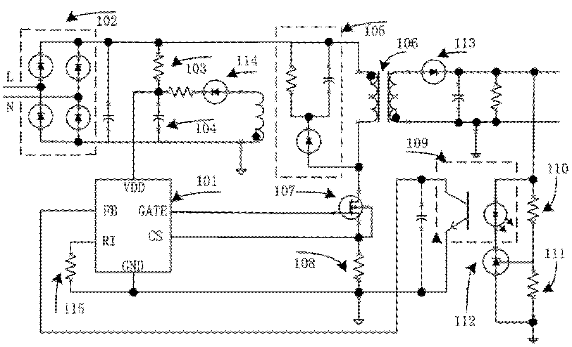
[0048] refer to figure 1 , is a low standby power consumption AC / DC switching power supply system application structure block diagram of the present invention. At the beginning of power-on, the power switch tube 107 is turned off, and the AC power supply charges the capacitor 104 through the bridge rectifier circuit 102 through the start-up resistor 103. When the voltage on the capacitor 104 is higher than the chip UVLO_OFF, the PWM switching power supply 101 starts and sends an enable The signal triggers the conduction of the power switch tube 107; during the conduction period of the power tube 107, the current flowing through the primary inductance of the transformer 106 flows through the CS peak current detection resistor 108 with a controlled rising slope, and the PWM switching power supply 101 detects the CS peak current detection resistor 108 to control the...


PUM


Abstract

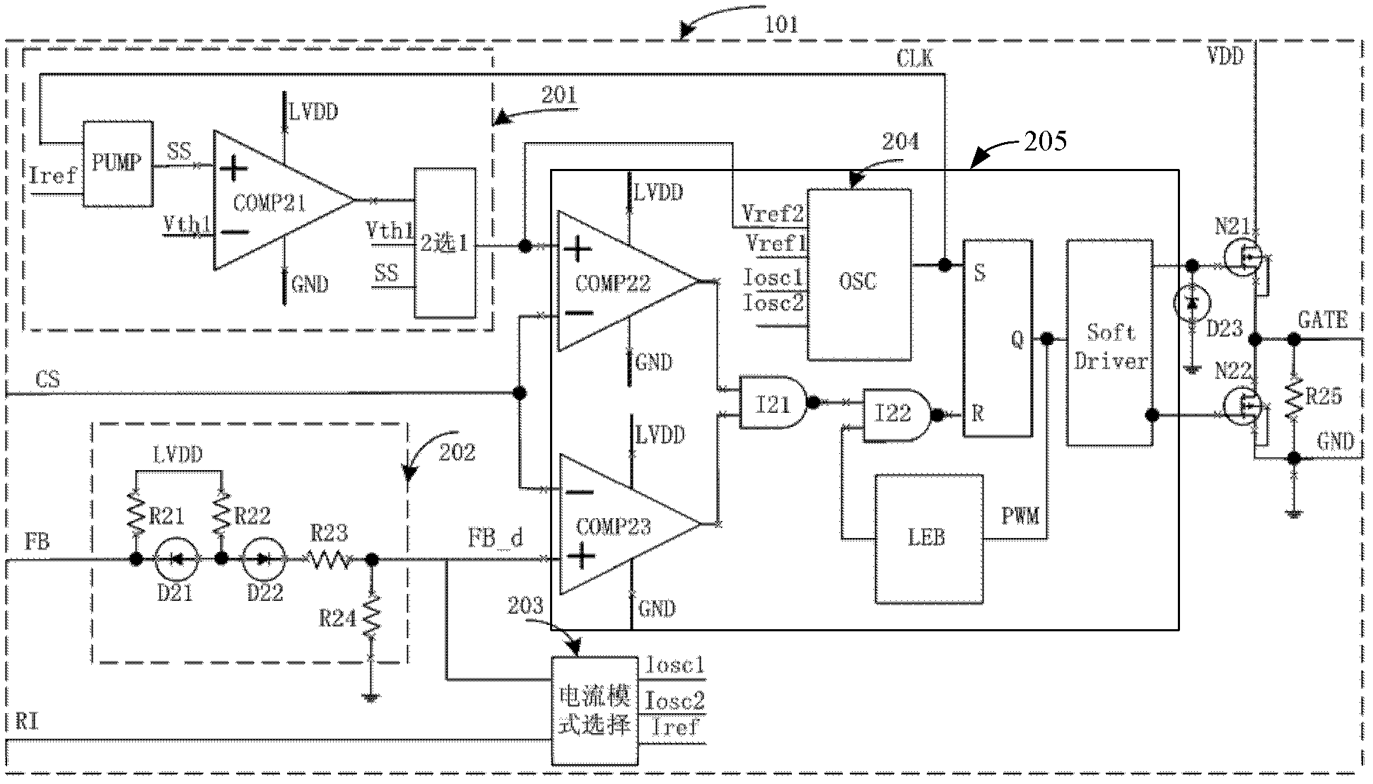
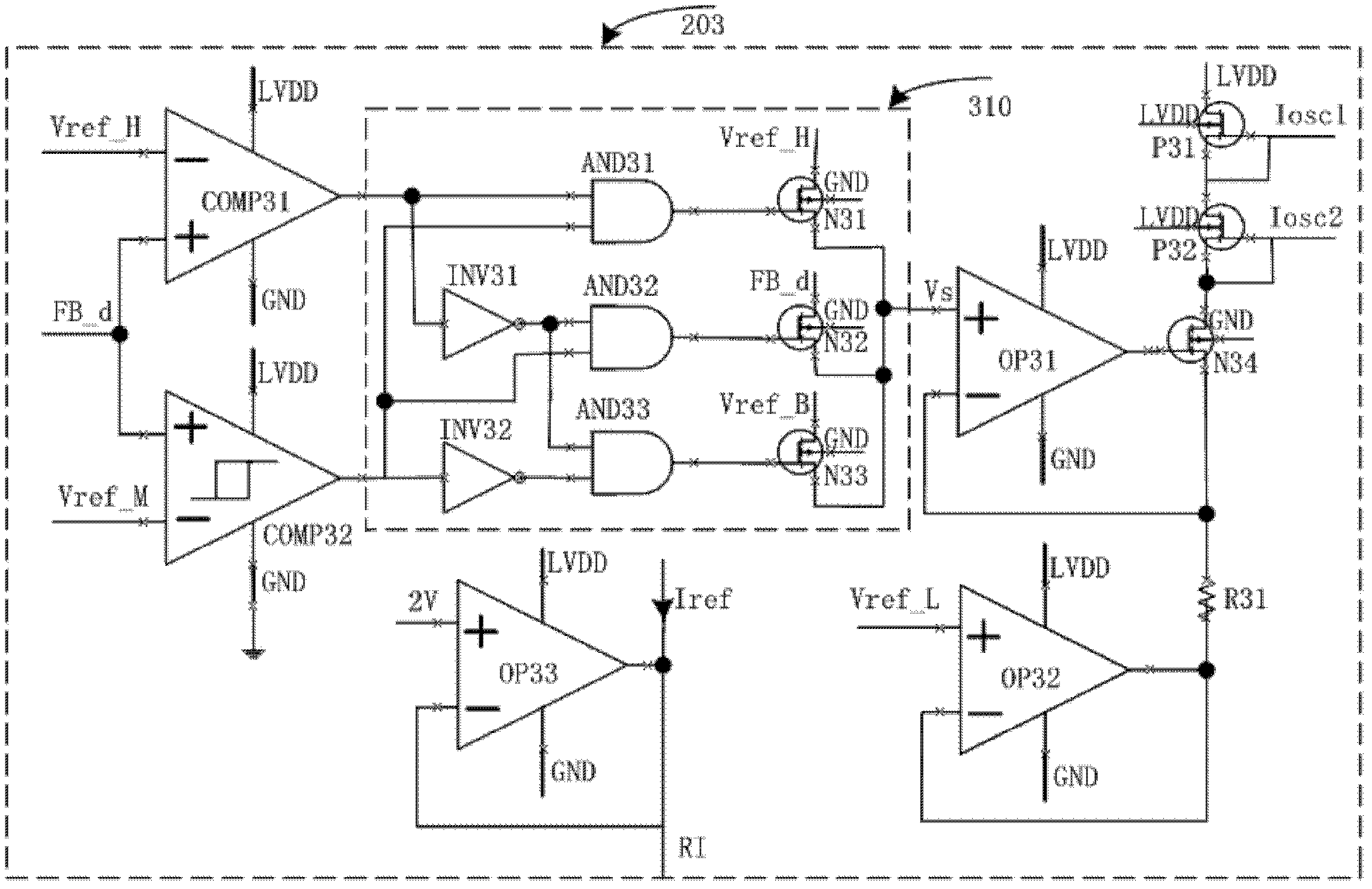
The invention provides a pulse width modulation switching power supply controller and a switching power supply and belongs to the technical field of electronic integrated circuits. The pulse width modulation switching power supply controller and the switching power supply are widely applied to a PWM (Pulse Width Modulation) mode AC / DC (Alternating Current / Direct Current) switching power supply system. The PWM controller comprises an FB (Feed Back) sampling circuit, a current mode selecting circuit, a square wave generating circuit and the like. The pulse width modulation switching power supply controller has the advantages of being capable of achieving self-adaption of the system working frequency under different loads and reducing standby power consumption of the switching power supply.

Description

technical field [0001] The invention relates to the technical field of basic electronic circuits, in particular to a pulse width modulation switching power supply controller and a switching power supply. Background technique [0002] With the increasing awareness of global environmental protection, more efficient use of energy has become a global consensus, so in recent years electronic products and their power supplies have begun to be restricted by energy-saving regulations, such as the California Energy Commission (CEC) Energy-saving regulations, and the "Energy Star (Energy Star)" label program, etc. In addition to these energy-saving specifications, another new specification that has attracted attention is "standby power consumption." According to statistics, the power consumption of electronic products in standby mode accounts for 3%-13% of the world's electricity, so the power consumption in standby mode has also drawn up clear specifications, and low standby power c...

Claims


Application Information

Patent Timeline
Patent Type & Authority Applications(China)
IPC IPC(8): H02M7/217
Inventor 朱樟明唐波
Owner 成都启臣微电子股份有限公司
Learn More