Ceramic component and method for producing a ceramic component

A technology of devices and ceramics, which is applied in the field of manufacturing such devices, can solve the problems of accuracy limitation, high total capacitance value, capacitance cannot be arbitrarily reduced, etc., and achieve the effect of tolerance balance and small capacitance

Active Publication Date: 2013-07-17
EPCOS AG
View PDF11 Cites 8 Cited by
  • Summary
  • Abstract
  • Description
  • Claims
  • Application Information

AI Technical Summary

Problems solved by technology

[0004] The capacitance of such components cannot be reduced arbitrarily, since in particular the outer electrodes would lead to relatively high overall capacitance values ​​in the case of a ceramic matrix with a high dielectric constant
In addition, the precision with which the comb-shaped internal electrodes are placed (for example by means of screen printing) is limited, so that tolerances can result in the capacitance of the components

Method used


Image

  • Ceramic component and method for producing a ceramic component
  • Ceramic component and method for producing a ceramic component
  • Ceramic component and method for producing a ceramic component

Examples


Embodiment Construction

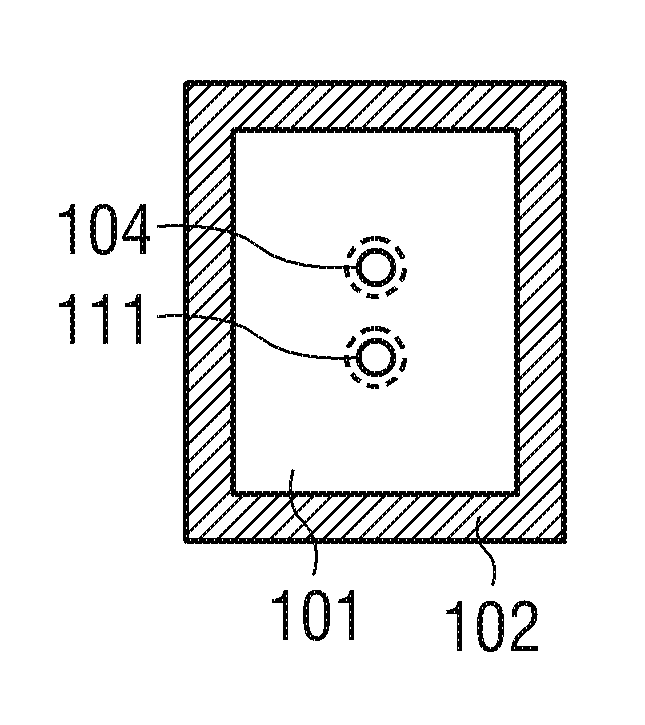
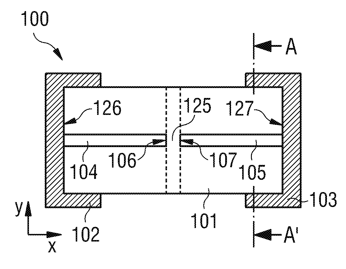
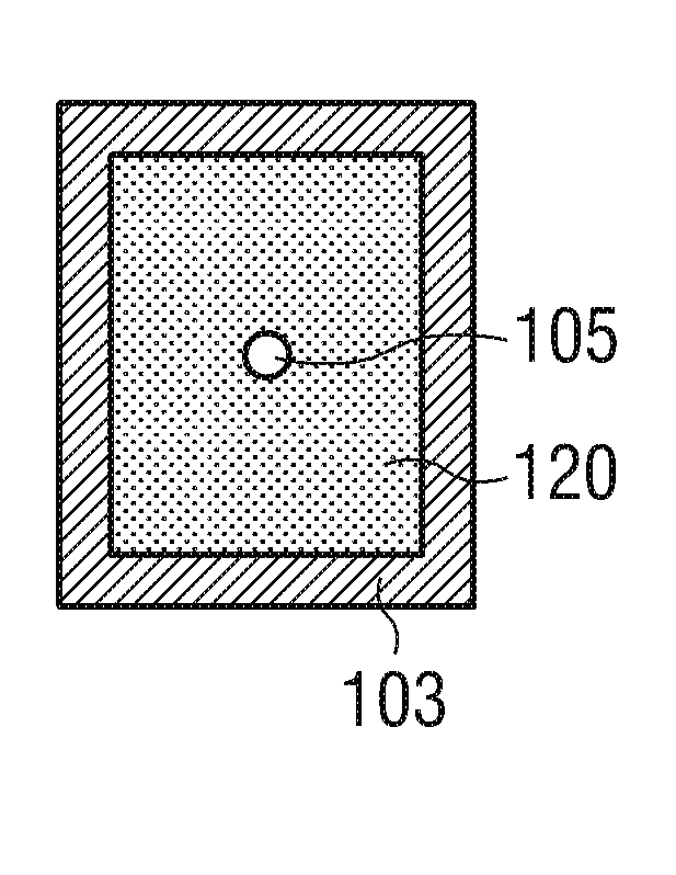
[0022] FIG. 1A shows a ceramic device 100 in cross-sectional view. The ceramic component has a base body 101 which consists of ceramic layers. Connecting contacts 102 , 103 for electrical contacting with component 100 are mounted on two opposite sides 126 , 127 . The longitudinally extending via electrodes 104 extend from the side surface 126 into the base body 101 . A further via electrode 105 extends into the base body 101 starting from the side surface 127 . The via electrode extends as far as the active region 125 in which, for example, a varistor ceramic is arranged. Via electrodes 104 and 105 respectively have faces 106 and 107 extending perpendicular to the longitudinal direction at ends facing away from connection contacts 102 and 103 respectively, which are electrically coupled to via electrodes 104 and 105 respectively.

[0023] The ceramic layers of the base body 101 are arranged in a layer stack. The layers extend planarly in the Y direction of FIG. 1 and are s...


PUM


Abstract

A ceramic component (100) comprises a basic body (101) with two connecting contacts (102, 103) fitted thereon. The component (100) has a first longitudinally extended via electrode (104) and a second longitudinally extended via electrode (105), said electrodes each being coupled to one of the connecting contacts (102, 103). The first via electrode (104) and the second via electrode (105) each have an extended area (106, 107) in projection in the longitudinal direction. For production purposes, a plurality of ceramic layers (117, 118, 119) is layered to form a layer stack, which forms the basic body (101), and the two via electrodes (104, 105) are introduced into the layer stack transversely to the layer sequence.

Description

technical field [0001] The present invention relates to ceramic devices, such as varistors, and to methods for manufacturing such devices. Background technique [0002] To protect high-frequency circuits from damage due to electrostatic discharge, varistors can be used. In such electronic components, the resistance depends on the voltage and suddenly decreases above a certain threshold voltage. As a result, loads in the event of high voltage application can be dissipated via the varistor. [0003] Conventional multilayer varistors have external connection contacts from which comb-shaped internal electrodes extend into the ceramic base body. Such a multilayer varistor is shown, for example, in DE19931056. [0004] The capacitance of such components cannot be reduced arbitrarily, since in particular the outer electrodes would lead to comparatively high overall capacitance values ​​in the case of a ceramic base body with a high dielectric constant. Furthermore, the precisio...

Claims


Application Information

Patent Timeline
IPC IPC(8): H01C7/105H01C7/18H01C7/10
CPCH01C7/105H01C7/18H01C7/1006
Inventor T.费希廷格G.普德米希
Owner EPCOS AG
Why Eureka
Try Eureka