Structure for output-stage film capacitor in power conditioner
A film capacitor and power regulator technology, applied in capacitors, irreversible DC power input conversion to AC power output, photovoltaic power generation, etc., can solve the problems of film damage, insulation breakdown, and high internal pressure of film capacitor components. To achieve the effect of preventing heat generation or capacitance reduction, and preventing abnormal breakdown
Inactive Publication Date: 2013-07-17
ORMON CORPORATION
8 Cites 0 Cited by
AI-Extracted Technical Summary
Problems solved by technology
If the gas remains inside without releasing the gas to the outside, the internal pressure of the film capacitor element becomes unfavorably high
[0007] As a result, the...
Method used
[0040] The present invention is constructed so that even in the film capacitor element constituting the structure of the output stage film capacitor used in the power conditioner, insulation is caused by a high voltage instantaneously generated due to a lightning strike or the like just in the vicinity of the power conditioner installation area breakdown, and also prevent harmonic currents from being generated due to heat generation or capacitance reduction caused by insulation degradation associated with insulation breakdown.
[0051] In addition, a thermal fuse 16 is also directly attached to the long-side forming side 6b in the substantially cuboid film capacitor element 6A, so that the temperature rise due to the high voltage of the film capacitor element 6A can be surely sensed. .
[0055] Furthermore, according to the first embodiment having the above-described structure, since the thermal fuse 16 is directly attached to the short-side forming side 6a and the long-side forming side 6b, which are the outer surfaces of the film capacitor element 6A, Mounting of the thermal fuse 16 is simple, and the thermal fuse 16 can also be applied to the existing film capacitor element 6A.
[0057] According to the first embodiment having the above structure, in addition to the short side forming the side 6a, the thermal fuse 16 is directly attached to the outer surface of the long side forming the side 6b, which makes it possible to capture the film capacitor element without omission A temperature change of 6A makes it possible to ensure the disconnection function due to the application of high voltage. As a result, even if insulation breakdown is caused in the film capacitor element 6A, it is possible to prevent high-frequency current from being generated due to heat generation or reduction in capacitance caused by insulation degradation involved in the above-mentioned insulation breakdown.
[0058] Furthermore, according t...
Abstract
The present invention has a film capacitor element (6A) as a low-pass filter for blocking off high-frequency waves generated by an inverter circuit (5), the film capacitor element being disposed between the inverter circuit (5) for converting the DC power of a power supply (1) to AC power and outputting the AC power, and an interlinking relay (7) for blocking interlinking connections between the power supply (1) and a system power supply (4). In this case, the temperature of the film capacitor element (6A) is detected by directly connecting a temperature fuse (16) to the film capacitor element (6A).
Application Domain
Single network parallel feeding arrangementsEmergency protective arrangements for automatic disconnection +3
Technology Topic
Film capacitorEngineering +6
Image
Examples
- Experimental program(2)
Example Embodiment
[0041] Embodiment 1
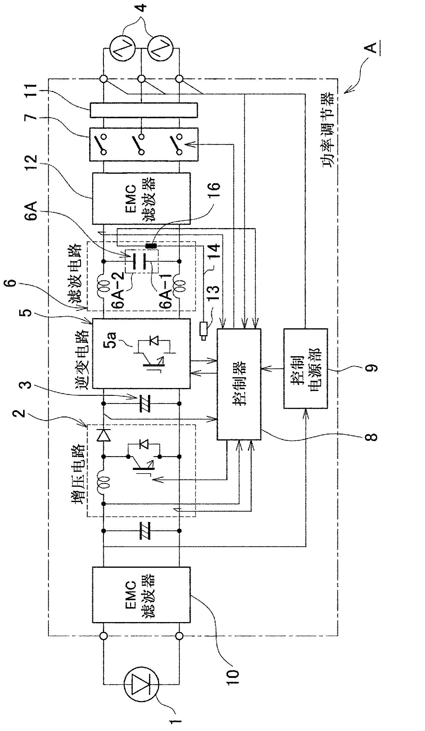
[0042] Next, we will use Figure 1 to Figure 4 A first embodiment according to the present invention is described. In the following description, the same reference numerals will be used to describe Figure 5 The corresponding structure of the conventional technology is shown.
[0043] like figure 1 As shown, a power conditioner A that converts DC power from a power source (such as a distributed power source according to the first embodiment of the present invention) into AC power synchronized with the system power source has a boost circuit 2 that increases the power from the power source 1 DC power (such as a distributed power source); electrolytic capacitor 3, smoothing the DC power increased in the booster circuit 2; inverter circuit 5, converting the DC power smoothed in the electrolytic capacitor 3 into synchronization with the system power supply 4 A filter circuit 6, which applies filtering processing to the AC power converted in the inverter circuit 5; an interconnection relay 7, which blocks the interconnection between the power supply 1 and the system power supply 4; the controller 8, which acts as a control The switching element 2a in the voltage circuit 2, the switching element 5a in the inverter circuit 5, or the CPU for driving the interconnection relay 7; and the control power supply section 9, which supplies the required power to the controller 8 as control power, thereby supplying the load to the load. The AC power subjected to the filtering process in the filter circuit 6 (such as a home appliance) is supplied.
[0044] In addition, the power conditioner A has: an input stage EMC filter 9, which is provided between the power supply 1 and the booster circuit 2 to block electromagnetic interference and the like from the power supply 1; and an output stage EMC filter 12, which blocks Electromagnetic interference or the like from the overvoltage absorbing element 11 , which absorbs high voltage, eg, lightning overvoltage from the system power supply, or lightning overvoltage from the system power supply 4 through the interconnection relay 7 .
[0045] In addition, the filter circuit 6 has a thin-film capacitor element 6A as a low-pass filter for blocking high-frequency waves generated by the inverter circuit 5 .
[0046] Therefore, in the power conditioner A, as in the conventional power conditioner, the output stage EMC filter 12 acts as a low-pass filter, and if a high voltage (eg, lightning overvoltage) is made to reach the system power supply 4 from the outside, etc., Then, the high voltage is blocked to prevent the high voltage from entering the filter circuit 6 .
[0047] In addition, the temperature regulator A has a temperature sensor, for example, the thermistor 13 that detects the internal temperature of the controller 8, which controls the switching of the inverter circuit 5 so that the output of the inverter circuit 5 is synchronized with the AC power of the system power supply and the thermistor 13 is connected to the controller 8 through the temperature sensor connection circuit 14 .
[0048] Further, the thin film capacitor element 6A constituting the filter circuit 6 is formed into a substantially rectangular parallelepiped in a state where a dielectric film (made by vapor-depositing an aluminum foil on a film made of synthetic resin) is wound several times into a ring shape shape, the electrode terminals 6A-1 are vapor-deposited to both ends of the dielectric film, respectively, and, in a state where the pair of electrode terminals 6A-1 appear outside, the thin-film capacitor element 6A is accommodated in, for example, a synthetic resin into the capacitor case 6A-2. The corresponding electrode terminals 6A- 1 are mounted on the electrode patterns of the printed circuit board 15 .
[0049] A plurality of thermal fuses 16 are directly attached to the surface of the substantially rectangular parallelepiped film capacitor element 6A. The outside of each thermal fuse 16 forms a flat mounting surface 16a, and at the same time, each thermal fuse 16 may be directly attached to the side portion of the film capacitor element 6A with an adhesive or the like, in this embodiment, possibly where it is It is directly attached to the film capacitor element 6A in a state of being sandwiched and supported between the surface of the film capacitor element 6A and the inner surface of the capacitor case 6A-2. Obviously, since each thermal fuse 16 senses the temperature of the film capacitor element 6A and is activated, it can be attached directly inside the film capacitor element 6A.
[0050] As an arrangement configuration for arranging the thermal fuse 16 to the film capacitor element 6A, the thermal fuse 16 is directly attached to at least the short side forming side surface 6a in the rectangular parallelepiped film capacitor element 6A. The above-mentioned short-side forming side surfaces 6a correspond to the folded surrounding portion of the dielectric film wound in a ring shape, and, at these positions, heat generation due to high voltage is more likely to be caused than at other positions.
[0051] Furthermore, the thermal fuse 16 is also directly attached to the long side forming side 6b in the substantially rectangular parallelepiped film capacitor element 6A, so that the temperature rise due to the high voltage of the film capacitor element 6A can be surely sensed.
[0052] like figure 1 As shown, each temperature fuse is arranged in series with the temperature sensor connection circuit 14, the thermistor 13 as a temperature sensor is connected with the temperature sensor connection circuit 14, the temperature sensor detects the internal temperature of the controller 8, and the controller 8 controls the reverse The switching of the inverter circuit 5 is operated so that the inverter circuit 5 outputs the AC power synchronized with the AC power of the system power supply 4 .
[0053] In the first embodiment according to the present invention having the above-described structure, since the temperature fuse 16 is directly attached to the film capacitor element 6A to sense the temperature of the film capacitor element 6A, when the temperature of the film capacitor element 6A reaches a predetermined temperature or higher (caused by a high voltage momentarily generated by a lightning strike, etc., just near the installation area of power conditioner A), immediately open the thermal fuse. Thereby, no short-circuit current flows in the film capacitor element 6A, which prevents abnormal breakdown of the film capacitor element 6A, and the temperature sensor connection circuit 14 is disconnected due to the disconnection of the temperature fuse, as a result, the power conditioner can be made The drive control circuit of A is disconnected, so that the operation of power conditioner A can be stopped safely.
[0054] That is, according to the structure of the first embodiment, the immediate disconnection of the temperature fuse 16 to which the high voltage is applied causes the temperature sensor connection circuit 14 to be disconnected to stop the driving of the controller 8 so that the short-circuit current is no longer in the film capacitor flow in the element 6A, which can prevent abnormal breakdown of the film capacitor element 6A, and can safely stop the operation of the power conditioner A by itself.
[0055] Furthermore, according to the first embodiment having the above-described structure, since the thermal fuse 16 is directly attached to the short-side forming side 6a and the long-side forming side 6b (both of which are the outer surfaces of the film capacitor element 6A), the thermal fuse The installation of the thermal fuse 16 is easy, and the thermal fuse 16 can also be applied to the existing film capacitor element 6A.
[0056] Further, according to the first embodiment having the above-described structure, since the short-side forming side surfaces 6a in the substantially rectangular parallelepiped film capacitor element 6A are the folded surrounds of the film on which the aluminum foil is vapor-deposited, at these positions, It is more likely to cause heat generation due to high voltage than at other locations (for example, forming the side surface 6b on the long side). This sensitizes the temperature sensing function of the thermal fuse 16, so that the thermal fuse is opened at an earlier stage, so that the abnormal breakdown of the film capacitor element 6A can be prevented more surely.
[0057] According to the first embodiment having the above-described structure, the temperature fuse 16 is directly attached to the outer surface of the long-side forming side 6b in addition to the short-side forming side 6a, which makes it possible to capture the temperature of the film capacitor element 6A without omission changes, so that the disconnection function due to the application of high voltage can be ensured. As a result, even if insulation breakdown is caused in the thin film capacitor element 6A, high-frequency current can be prevented from being generated due to heat generation or capacitance reduction due to insulation deterioration involved in the above-described insulation breakdown.
[0058] Furthermore, according to the first embodiment having the above-described structure, each thermal fuse 16 has the flat mounting surface 16a, which enables the flat mounting surface 16a to be attached to the outer surface of the film capacitor element 6A, so that the thermal fuse 16 can be attached It is simpler and mounted on the film capacitor element 6A in a stable state.
Example Embodiment
[0059] Embodiment 2
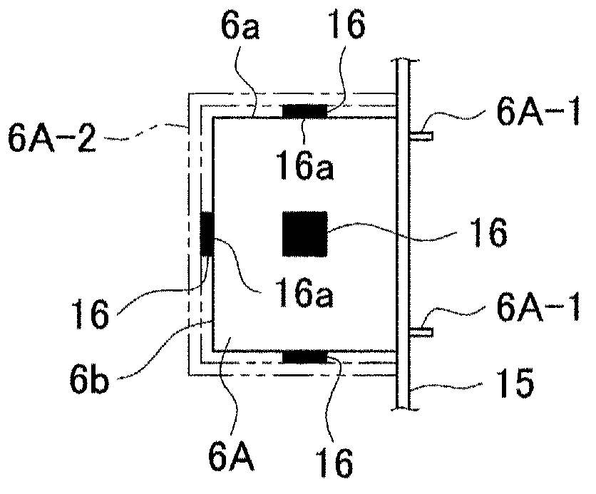
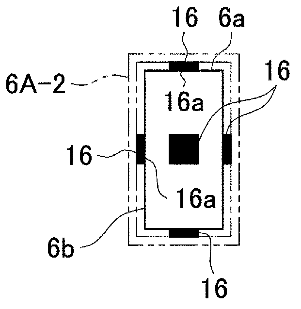
[0060] Next, we will use Figure 4 A second embodiment according to the present invention is described. according to Figure 4 , the second embodiment has a structure similar to that of the first embodiment in which the thermal fuse 16 is directly attached to the short-side forming side 6a and the long-side forming side 6b of the film capacitor element 6A or the like, except that the For example, two film capacitor elements 6A are accommodated in the capacitor case 6A- 2 in a state where the surfaces of one side are abutted to each other to increase the capacitor capacitance, and one thermal fuse 16 is sandwiched and mounted on the two adjacent to each other. between the side surfaces. Furthermore, the temperature fuse 16 is connected in series in the temperature sensor connection circuit 14 in the power conditioner A as in the first embodiment.
[0061]Therefore, in the second embodiment, as in the first embodiment, since the temperature fuse 16 is directly attached to the film capacitor element 6A to sense the temperature of the film capacitor element 6A, when the temperature of the film capacitor element 6A is When the temperature reaches a predetermined temperature or higher (caused by a high voltage instantaneously generated by a lightning strike or the like just near the installation area of the power conditioner A), the temperature fuse is immediately opened so that no short-circuit current flows in the film capacitor element 6A, This prevents abnormal breakdown of the film capacitor element 6A. In addition, the disconnection of the temperature fuse causes the temperature sensor connection circuit 14 to be disconnected, and as a result, the drive control circuit of the power conditioner A can be disconnected, so that the operation of the power conditioner A can be stopped safely.
[0062] That is, also, according to the structure of the second embodiment, the immediate disconnection of the temperature fuse 16 to which the high voltage is applied causes the temperature sensor connection circuit 14 to be disconnected to stop the driving of the controller 8, and the short-circuit current is no longer flow in the film capacitor element 6A, which can prevent abnormal breakdown of the film capacitor element 6A, and can safely stop the operation of the power conditioner A by itself.
[0063] Also, according to the second embodiment having the above-described structure, since the thermal fuse 16 is directly attached to the short-side forming side 6a and the long-side forming side 6b (both of which are the outer surfaces of the film capacitor element 6A), the temperature The installation of the fuse 16 is easy, and the thermal fuse 16 can also be applied to the existing film capacitor element 6A.
[0064] Furthermore, also according to the second embodiment having the above-described structure, since the short-side forming side 6a in the substantially rectangular parallelepiped film capacitor element 6A is the folded surrounding portion of the film on which the aluminum foil is vapor-deposited, in these The position is more likely to cause heat generation due to high voltage than other positions (for example, forming the side surface 6b on the long side). This sensitizes the temperature sensing function of the thermal fuse 16 to open the thermal fuse at an earlier stage, so that abnormal breakdown of the film capacitor element 6A can be more surely prevented. As a result, even if insulation breakdown is caused in the film capacitor element 6A, it is possible to prevent high-frequency current from being generated due to heat generation or capacitance reduction due to insulation deterioration involved in the above-described insulation breakdown.
[0065] Also, according to the second embodiment having the above-described structure, the thermal fuse 16 is directly attached to the outer surface of the long-side forming side 6b in addition to the short-side forming side 6a, which enables the film capacitor to be captured without omission The temperature of the element 6A changes, and the disconnection function due to the application of high voltage can be ensured.
[0066] Furthermore, also according to the second embodiment having the above-described structure, each thermal fuse 16 has a plane mounting surface 16a, which enables the plane mounting surface 16a to be attached to the outer surface of the film capacitor element 6A, so that the thermal fuse can be fused The device 16 is simpler and is mounted on the film capacitor element 6A in a stable state.
[0067] Furthermore, accommodating the two film capacitor elements 6A in the capacitor case 6A-2 increases the surface area of the capacitor case 6A-2, and compared to the case where the two film capacitor elements 6A are accommodated in each capacitor case 6A-2 , which firmly supports the thermal fuse 16 sandwiched and supported between the capacitor case 6A-2 and the film capacitor element 6A.
PUM


Description & Claims & Application Information
We can also present the details of the Description, Claims and Application information to help users get a comprehensive understanding of the technical details of the patent, such as background art, summary of invention, brief description of drawings, description of embodiments, and other original content. On the other hand, users can also determine the specific scope of protection of the technology through the list of claims; as well as understand the changes in the life cycle of the technology with the presentation of the patent timeline. Login to view more.