Special spiral staggered positioning desalter for nuclear power plant

A positioning type, nuclear power plant technology, applied in the field of nuclear power plants, can solve the problems of reducing the efficiency of dismantling and washing, reducing the service life of filters, and high processing difficulty, and achieves the effects of improving mechanical properties and filtration efficiency, prolonging service life, and avoiding fatigue fractures.

Active Publication Date: 2014-10-29
南通市崇川科技创业服务中心有限公司
View PDF5 Cites 0 Cited by
  • Summary
  • Abstract
  • Description
  • Claims
  • Application Information

AI Technical Summary

Problems solved by technology

The wire-wound filter head is easy to be damaged. When the steel wire is wound, it needs to be fixed on the frame by spot welding. The welding deformation is large, the strength of the steel wire is low, and it is easy to deform. The gap between the steel wire and the steel wire is difficult to control.
The filter tube of the laminated filter head is composed of several filter sheets with the same structure. Each filter sheet has a symmetrical small boss in the cross direction, which is integrated with the filter sheet. Therefore, after several sheets are stacked and combined Four ribs are formed in the axial direction, and four water passage gaps are formed at equidistant intervals along the circumference between the connected two pieces. This device is not easy to be damaged compared with the wire-wound filter head. Its disadvantages are:
[0004] 1. Since the height of the small bosses is prone to deviation during production, and the water gap between the sheets is controlled by the contact of the small bosses at four parts, this will make the size of the water gap uneven, If the gap is too large, the ion exchange resin will be lost.
[0005] 2. Since there are four small bosses between every two adjacent filter pieces, this also reduces the water permeability of the filter head
[0007] 1. The processing procedure of the filter tube is cumbersome, and the processing precision is very high, and the processing difficulty is relatively high;
[0008] 2. Due to the vibration of the long-term water flow impact on the filter, individual filters will be fatigued and broken under repeated high-frequency bending
Due to the limited length of the filter head, increasing the thickness of the filter will undoubtedly reduce the number of water gaps, which will greatly reduce the water permeability of the filter head and reduce the use efficiency of the device
[0009] 3. In the above scheme, all the filters are an inseparable whole, which brings great difficulty to the regular dismantling and washing work and greatly reduces the efficiency of dismantling and washing work
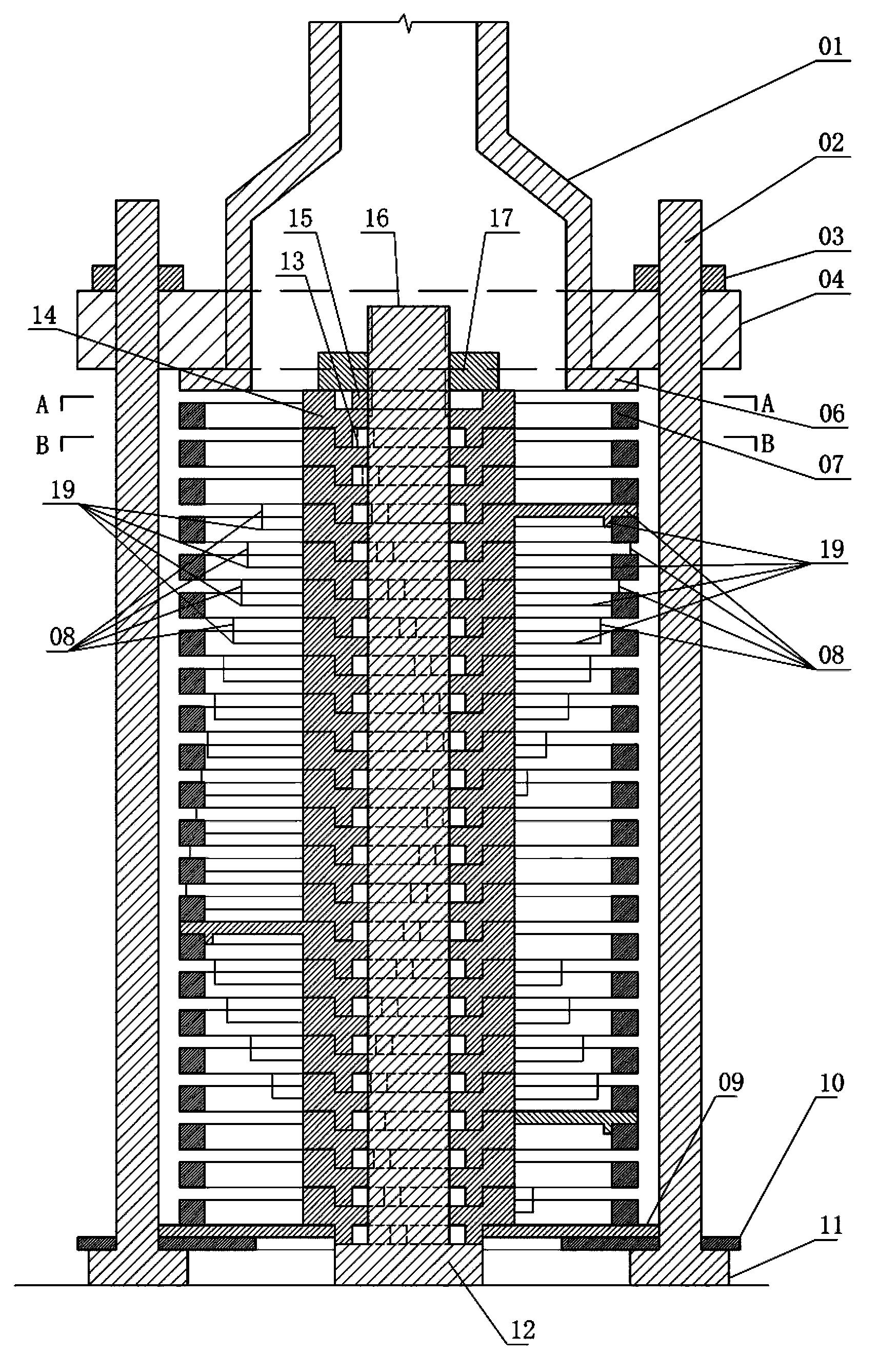
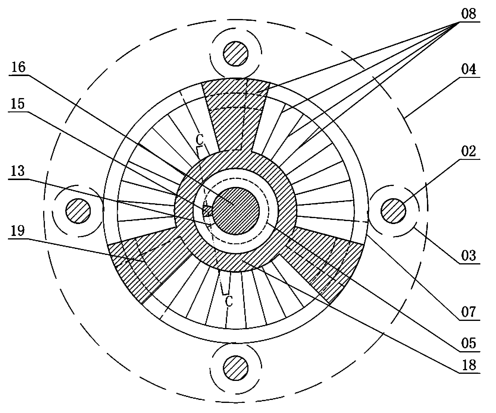
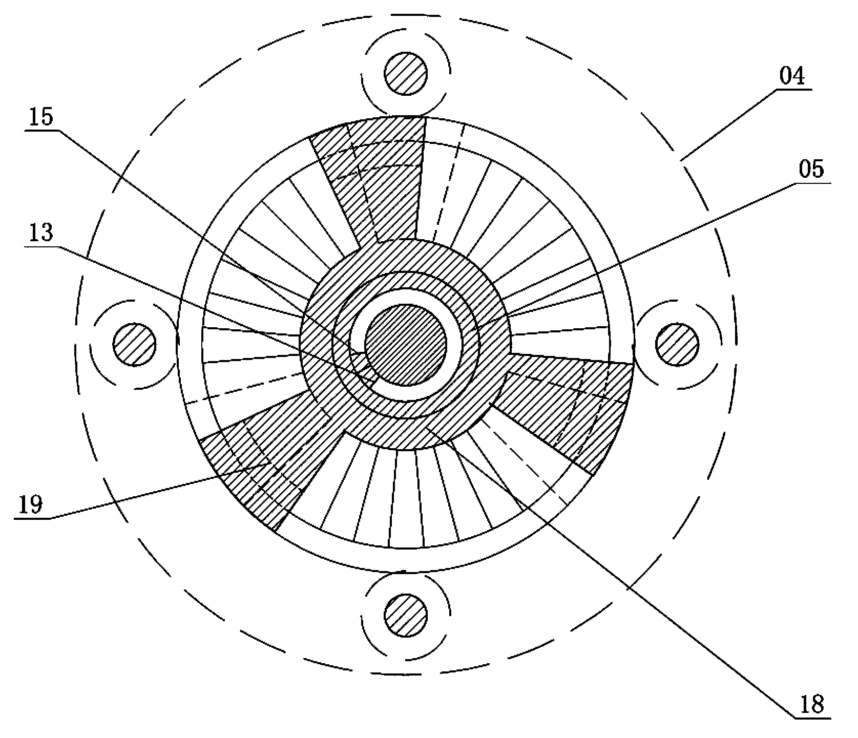
[0011] 1. Since each end piece is fixed by a pull piece and three fixed tie rods that run through the filter head of the desalter longitudinally, this determines that the three end pieces of each layer are in the same position in the horizontal direction. Therefore, the overlapping end sheets will form three ribs in the longitudinal direction of the filter device, and the part of the filter sheet at the position of these three ribs will have stronger rigidity, while the rest of the filter sheet will not be supported by any other components. Rigidity is weak, therefore, the rigidity distribution of each filter is uneven
Under the long-term impact of water flow, this uneven distribution of rigidity will cause the filter to break due to long-term high-frequency vibration
This undoubtedly reduces the durability and impact strength of the device
[0012] 2. The high-frequency vibration of the filter not only reduces the service life of the filter, but more importantly, because the elastic deformation that occurs during the vibration will change the gap width between two adjacent filters, so that Reduced filtration efficiency of ion exchange resins
[0013] 3. Since the positioning rib in the above scheme is closely attached to the end of each end piece, and its arc length exceeds the length of the end piece, on the one hand, it will block the water outlet and reduce the water outlet efficiency of the device; at the same time, The positioning ribs can only limit the horizontal position of the end piece, but the three tie rods already have this function. Therefore, the existence of the positioning ribs also causes waste of materials
Increased manufacturing cost of the device
[0014] 4. Since each sheet body composed of an end piece and a tie piece must simultaneously and accurately set its three collar pieces on the three tie rods that form a dynamic cooperation relationship with it, it has a high assembly accuracy requirement , so the assembly process is not efficient
[0015] 5. In this device, the alternately superimposed filter pieces and end pieces are pressed tightly, relying on three tie rods located in the middle of the device, and there is no force-applying structure at the outer edges of the end pieces and filter pieces to make them The edge is tightly combined, and such uneven force will lead to a difference in the height position between the middle and the edge of the sheet body composed of the end sheet and the tie sheet, thereby causing a certain degree of deformation, and this deformation is for the adjacent filter The uniformity of the gap between the sheets is very unfavorable
thus also reducing the filtering effect of the unit
[0016] 6. In this device, due to the blockage of the top plate at the water inlet, the water can only pass through the three limited-area water holes opened on the top plate, which undoubtedly reduces the water passing efficiency of the device; but if the three The opening area of ​​the water hole will inevitably reduce the strength of the top plate, affecting its pressure and fixing effect on the filter piece and end piece, which is also a pair of difficult contradictions

Method used


Image

  • Special spiral staggered positioning desalter for nuclear power plant
  • Special spiral staggered positioning desalter for nuclear power plant
  • Special spiral staggered positioning desalter for nuclear power plant

Examples


Embodiment Construction

[0043] The present invention will be further described below in conjunction with the accompanying drawings and embodiments.

[0044] The special spiral staggered positioning desalter filter device for nuclear power plants consists of connecting pipe 01, pull rod 02, pull rod nut 03, positioning ring 04, upper pressure ring 06, filter piece 07, spacer 08, bottom ring 09, lower pressure ring 10, The pull connection end post 11, the axial end post 12, the stem post 16, the stem post nut 17, the protruding strip 19 and the limit sleeve are formed.

[0045] The limit sleeve disc is composed of the lower positioning ring 05, the lower limit block 13, the shaft center sleeve 14, the upper limit block 15 and the upper positioning ring 18. In the same position limit sleeve disc, the shaft center sleeve 14 is a ring body, There is an annular upper positioning ring 18 integrated with the axial sleeve 14 on the edge of the upper surface of the axial sleeve 14, and the bottom surface of th...


PUM


Abstract

The invention relates to a nuclear power station technology field, particularly a filter of a spirally interlaced positioning type salt remover special for a nuclear power station, which is composed of an adapter, a pull bar, a pull bar nut, a positioning ring, an upper pressure ring, a filter disc, a spacing block, a bottom ring, a lower pressure ring, a pull connection end post, an axle center terminus post, a core post, a core post nut, a convex strip and spacing sleeve discs. An upper spacing block, which is an integral body with an axle center sleeve, is arranged on an internal edge of an upper surface of the axle center sleeve, a lower spacing block, which is an integral body with an axle center sleeve, is arranged on an internal edge of a lower surface of the axle center sleeve, and a vertical side face of the upper spacing block facing to a counterclockwise direction is aligned at a vertical surface of the lower spacing block facing to a clockwise direction, wherein the multiple spacing sleeve discs are superposed up and down to form a column shape. The spirally interlaced positioning type salt remover special for the nuclear power station has advantages of better filtration effect, longer service life, and more convenient assembly.

Description

technical field [0001] The invention relates to the technical field of nuclear power plants, in particular to a special helical staggered positioning desalter filter device for nuclear power plants. Background technique [0002] The inlets and outlets of the yin bed, yang bed, and wet bed of the water treatment equipment desalter of the existing nuclear power plant are all equipped with filter head devices, also known as water caps, which are used to prevent the passage of ion exchange resins, but can Purified water is passed through to obtain clean water. [0003] The existing filter head structures include wire-wound type and laminated type. The wire-wound filter head is easy to be damaged. When the steel wire is wound, it needs to be fixed on the skeleton by spot welding. The welding deformation is large, the steel wire has low strength and is easy to deform, and the gap between the steel wire and the steel wire is difficult to control. The filter tube of the laminated ...

Claims


Application Information

Patent Timeline
Patent Type & Authority Patents(China)
IPC IPC(8): B01D29/46
Inventor 梁德富
Owner 南通市崇川科技创业服务中心有限公司
Why Eureka
Try Eureka