A bracket laser cutting equipment

A laser cutting, laser cutting head technology, applied in laser welding equipment, welding equipment, metal processing equipment and other directions, can solve the problems of damaged laser, low laser peak power, uneven surface of the cutting seam, etc., to suppress damage and improve laser Effects of Power and Power Density

Active Publication Date: 2016-07-06
KUNSHAN THETA MICRO
View PDF6 Cites 0 Cited by
  • Summary
  • Abstract
  • Description
  • Claims
  • Application Information

AI Technical Summary

Problems solved by technology

During laser cutting, the peak power of the laser is low, and the vaporized and evaporated material will stick to the cutting edge, making the surface of the cutting kerf not smooth. At the same time, during laser cutting, the reflection of the surface of the workpiece is different for different materials, especially when cutting metal materials. What's more, part of the reflected return light returns to the laser along the original optical path, which will affect the normal operation of the laser. The reflected return light reaches a certain level, and even damages the laser
[0004] Since the stent is a high-precision medical device, every link of production, transportation, etc. needs to be strictly managed and traceable, and these are not available in existing laser cutting equipment, and the current existing technology is in the When the stent is cut, the laser peak power is low, and the reflected return light affects the normal operation of the laser, and the production process cannot be monitored in real time

Method used


Image

  • A bracket laser cutting equipment
  • A bracket laser cutting equipment
  • A bracket laser cutting equipment

Examples


Embodiment Construction

[0020] In order to make the object, technical solution and advantages of the present invention clearer, the present invention will be further described in detail below in conjunction with the accompanying drawings and embodiments. It should be understood that the specific embodiments described here are only used to explain the present invention, not to limit the present invention.

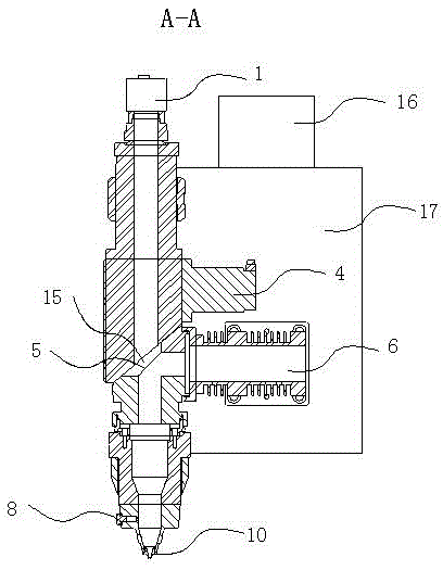
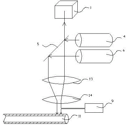
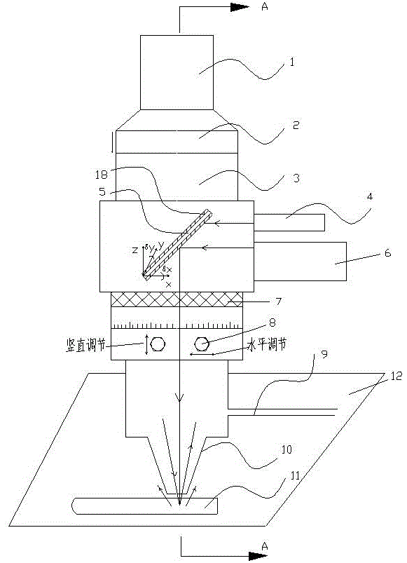
[0021] Please refer to figure 1 , figure 2 As shown, the stent laser cutting equipment of the present invention includes a laser cutting head, a Z-axis device 17, a servo motor 16 and a laser transmission optical path structure. Wherein, the top of the laser cutting head is provided with a CCD monitoring system 1 , and the bottom of the laser cutting head is provided with a cutting nozzle 10 . The laser transmission optical path structure includes an illumination light source 4 and a fiber laser 6 arranged on one side of the axis of the laser cutting head, a 45° reflector 5 arranged on the axis ...


PUM


Abstract

The invention discloses laser cutting equipment for stents. The laser cutting equipment comprises a laser cuing head, a Z-axis, a servo motor and a laser transmission light path structure, wherein the laser transmission light path structure comprises a lighting source and an optical fiber laser which are arranged on one side of the axis of the laser cutting head, a 450 reflecting mirror arranged on the axis of the laser cutting head, a focusing mirror arranged below the 450 reflecting mirror, and a protective mirror arranged below the focusing mirror, wherein a reflecting mirror cover plate is arranged above the 450 reflecting mirror. The laser cutting equipment for the stents, which is disclosed by the invention, has the advantages that the optical fiber laser is adopted, and multiple optical elements are used, so the laser power and the power density are greatly improved; the damage of return light to the laser is inhibited by the design of the laser transmission light path structure; and meanwhile, the whole machining process has traceability and a full life cycle management demand of the stents is satisfied.

Description

technical field [0001] The invention belongs to the technical field of laser fine processing, and in particular relates to a bracket laser cutting device used for laser cutting of medical brackets. Background technique [0002] With various acute and chronic vascular occlusive diseases seriously threatening human life safety and health, cardiovascular and cerebrovascular occlusive diseases are the biggest killer. A stent is a metal mesh structure implanted into a vascular lesion to improve blood flow in the lesion and support the blood vessel. Medical stents are generally implanted into the diseased part of the blood vessel through interventional surgery, and finally bonded to the inner wall of the blood vessel. Therefore, medical stents have strict requirements on the shape tolerance and surface finish of the stent. Laser micromachining has become the main processing method for medical inner stents because it is superior to traditional mechanical processing methods in cutt...

Claims


Application Information

Patent Timeline
Patent Type & Authority Patents(China)
IPC IPC(8): B23K26/38B23K26/064B23K26/70B23K101/06B23K26/14
Inventor 魏志凌宁军夏发平马秀云
Owner KUNSHAN THETA MICRO
Why Eureka
Try Eureka