Movable centre grinding device and grinding method thereof

A kind of top and lathe technology, applied in the direction of grinding drive device, grinding machine parts, grinding/polishing equipment, etc., can solve the problems of unable to meet the repair grinding, the accuracy error of the moving center axis, and eliminate the moving center mandrel. Axis offset, elimination of precision errors, easy installation and adjustment

Inactive Publication Date: 2013-07-24
CSSC HUANGPU WENCHONG SHIPBUILDING COMPANY
View PDF7 Cites 0 Cited by
  • Summary
  • Abstract
  • Description
  • Claims
  • Application Information

AI Technical Summary

Problems solved by technology

[0004] The purpose of the present invention is to overcome the problem that the existing active center grinding device cannot meet the requirements of repairing gr

Method used


Image

  • Movable centre grinding device and grinding method thereof
  • Movable centre grinding device and grinding method thereof

Examples


Embodiment Construction

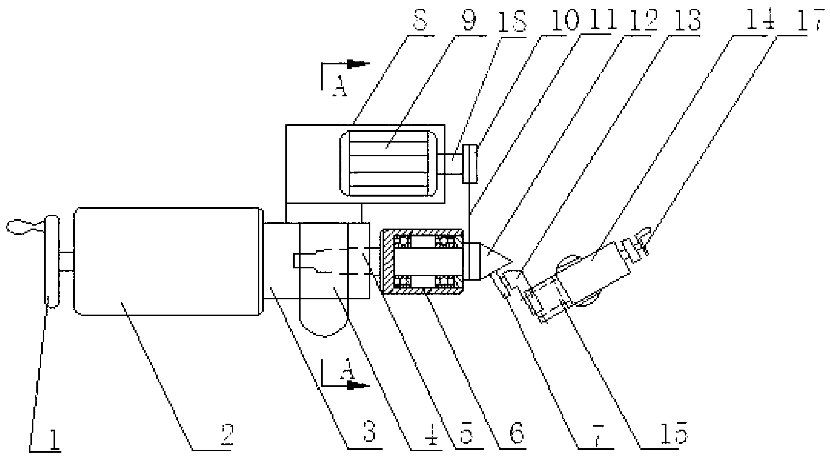
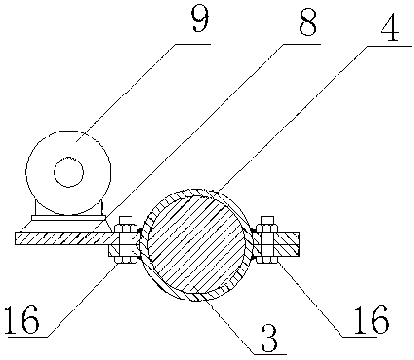
[0019] In order to overcome the problem that the existing active center grinding device cannot meet the requirements of repairing grinding and using the active center grinding with the same rotation reference, resulting in the existence of axis accuracy errors in the active center after grinding, this embodiment provides a figure 1 The movable top grinding device shown includes a lathe tailstock telescopic shaft 3 with an axial inner tapered hole at the end, a micro grinder 13 installed on the tool rest 15 of the small carriage 14 of the lathe (its end It is provided with a grinding wheel 7) and a stepless speed regulation motor 9 for driving the movable top mandrel 12 to rotate, and the stepless speed regulation motor 9 is installed on a horizontal support platform 8, which passes through two semicircle open sides The steel sleeve 4 clamps on the outer wall of the telescopic shaft 3 of the lathe tailstock, and the horizontal support platform 8 is welded on the steel sleeve 4 w...


PUM


Abstract

The invention provides a movable centre grinding device, which comprises a lathe tailstock telescopic shaft, a micro grinding machine and a stepless speed regulating motor, wherein the tip of the lathe tailstock telescopic shaft is provided with an axial inner taper hole; the micro grinding machine is arranged on a tool rest of a lathe small carriage; the stepless speed regulating motor is used for driving a movable centre mandrel to rotate; the stepless speed regulating motor is arranged on a horizontal supporting platform; and the horizontal supporting platform is arranged on the outer circle wall of the lathe tailstock telescopic shaft. Due to the adoption of the movable centre grinding device, the axis deviation, caused by rotation under different standards, of the movable centre mandrel is avoided, and accuracy errors caused by grinding with a conventional cylindrical grinding machine is eliminated; and the device has the advantages of simple structure, easiness, practicability, and easiness in installing and adjusting.

Description

technical field [0001] The invention belongs to the field of mechanical processing, and in particular relates to a movable top grinding device. Background technique [0002] In mechanical processing, when machining workpieces or shaft parts with a length-to-diameter ratio exceeding a certain range on a lathe, one end chuck must be clamped, and the other end must be clamped with a movable top support or two top support clamps to perform turning operations on the workpiece. Therefore, the precision of the top of the movement is very important. Its precision will directly affect the coaxiality and roundness of the workpiece after machining. However, after the movable top is used for many times, the machining accuracy of the workpiece is affected by the wear of the top part, which greatly increases the reject rate of the workpiece. Therefore, the top of the movement must be re-sharpened. The grinding method has been using a cylindrical grinder. Put the movable top taper hand...

Claims


Application Information

Patent Timeline
IPC IPC(8): B24B19/16B24B47/04
Inventor 何道生付永丽
Owner CSSC HUANGPU WENCHONG SHIPBUILDING COMPANY
Why Eureka
Try Eureka