Electromagnetic controllable mechanical brake parking device

A mechanical braking and controllable technology, applied in the direction of brake transmission, brake, railway braking system, etc., can solve the problems of complex system, tread wear, crack or peeling, etc., to achieve simple device structure and small occupied space. , the effect of convenient operation

Inactive Publication Date: 2013-07-24
TONGJI UNIV
View PDF4 Cites 14 Cited by
  • Summary
  • Abstract
  • Description
  • Claims
  • Application Information

AI Technical Summary

Problems solved by technology

[0002] As the brake device used in traditional rail transit vehicles, as far as the braking position is concerned, tread brakes or disc brakes are generally used. Most of the heat load is borne by the wheels or brake discs, and the heat is not conducive to rapid braking. Dissipation, when the vehicle is braked on the tread, the temperature of the wheel tread will increase rapidly. When it reaches a certain level, the tread will be worn, cracked or peeled off, which will not only affect the service life but also affect the driving safety. If the disc brak

Method used


Image

  • Electromagnetic controllable mechanical brake parking device
  • Electromagnetic controllable mechanical brake parking device
  • Electromagnetic controllable mechanical brake parking device

Examples


Example Embodiment

[0026] Example 1

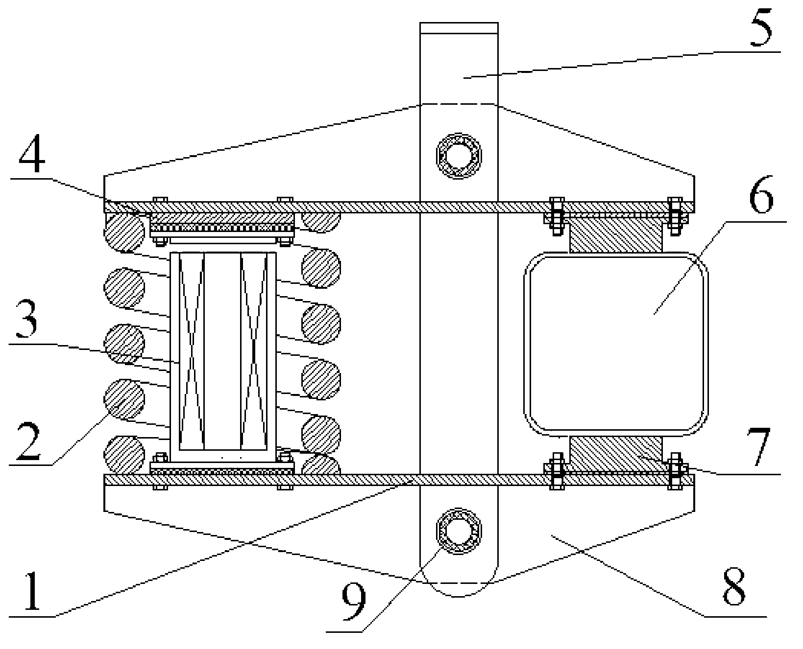
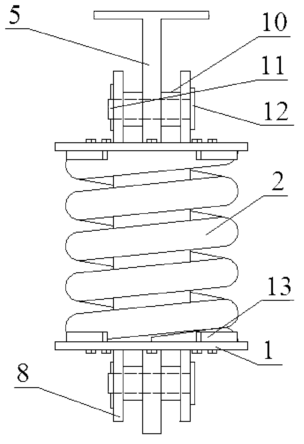
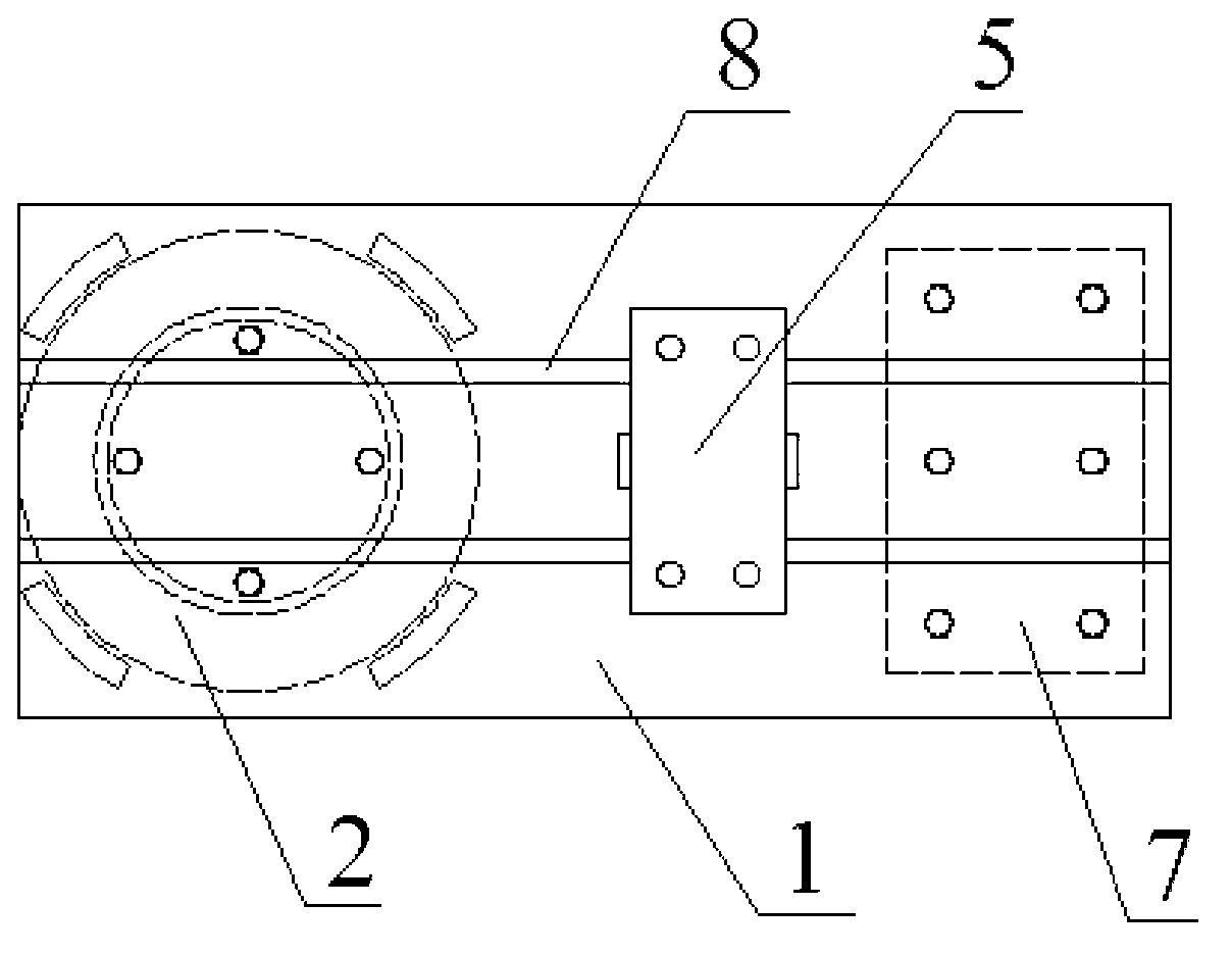
[0027] An electromagnetic controllable mechanical brake parking device, such as Figure 1 ~ Figure 3 As shown, it includes an action arm 1, an action arm mounting seat 5, a cylindrical compression spring 2, an electromagnet assembly 3, and a wear sheet 7. The action arm 1 is provided with two, and the action arm 1 is provided with two stiffener plates 8. The reinforcing rib plates 8 are respectively located on the front and rear sides of the working arm mounting base 5, and the reinforcing rib plates 8 and the upper and lower ends of the working arm mounting base 5 are rotationally connected by a pin 11. The two ends of the pin 11 are locked by the tooth bars 12. The stiffener plate 8 and the arm mounting seat 5 are both provided with mounting holes, the mounting hole is provided with a bushing 9, and the pin 11 is arranged in the bushing 9, between the stiffening plate 8 and the arm mounting seat 5 A positioning sleeve 10 is sleeved on the outer side of the ...

Example Embodiment

[0031] Example 2

[0032] The difference from Example 1 is:

[0033] The thickness of the adjusting shim 4 is 5 mm, the thickness of the insulating shim is 2 mm, and the diameter is 70 mm. The material of the insulating shim is a non-magnetic material selected from lead or copper. The length of the wear sheet 7 is 100 mm and the width is 50 mm.

[0034] The cylindrical compression spring 2 is made of 55Si2Mn steel wire with a diameter of 20mm. The cylindrical compression spring 2 has an intermediate diameter of 100mm, an effective number of turns of 3, a stiffness of 500N / mm, and a free height of 120mm. The force is 1000N.

[0035] The electromagnet assembly 3 includes an armature and a series coil. The series coil is composed of a wire with a diameter of 3mm wound around the armature. The diameter of the armature is 6cm. The number of turns of the series coil is 100 turns. The magnetic potential of the series coil is 1000 ampere turns. With a current of 0-20 A, the magnetic inducti...

Example Embodiment

[0036] Example 3

[0037] The difference from Example 1 is:

[0038] The thickness of the adjusting gasket 4 is 15 mm, the thickness of the insulating gasket 4 is 5 mm, and the diameter is 170 mm. The material of the insulating gasket 4 is a non-magnetic material selected from a palladium alloy. The length of the wear sheet 7 is 300 mm and the width is 150 mm. Cylindrical compression spring 2 is made of steel wire with a diameter of 40mm and 60Si2Mn. The diameter of cylindrical compression spring 2 is 200mm, the effective number of turns is 6, the stiffness is 1500N / mm, and the free height is 140mm. The force is 8000N.

[0039] The electromagnet assembly 3 includes an armature and a series coil. The series coil is composed of a wire with a diameter of 5mm wound around the armature. The diameter of the armature is 16cm. The number of turns of the series coil is 250 turns. The magnetic potential of the series coil is 1500 ampere turns. With a current of 0-20 A, the magnetic inductio...


PUM

PropertyMeasurementUnit
Diameteraaaaaaaaaa
Middle diameteraaaaaaaaaa
Stiffnessaaaaaaaaaa

Abstract

The invention relates to an electromagnetic controllable mechanical brake parking device which comprises action arms, an action arm installation seat, cylindrical compression springs, electromagnetic iron components and abrasion pieces. Two action arms are respectively connected on an upper end and a lower end of the action arm installation seat in a rotation mode, the cylindrical compression springs are arranged between the two action arms, two ends of each cylindrical compression spring are connected with the action arms on the upper side and the lower side respectively, the electromagnetic iron components are arranged inside the cylindrical compression springs and connected with the action arms on the upper side and the lower side, and two abrasion pieces are respectively arranged at the other end of each action arm. Compared with the prior art, electricity amount of the electromagnetic iron components is controlled to control frictional force among the abrasion pieces and a steel rail so as to achieve braking or parking of a vehicle, the abrasion pieces are compressed on the steel rail, most thermal load is born by the steel rail, the position of the vehicle is continuously moved, heat generated by the braking is rapidly dissipated on the steel rail, and the electromagnetic controllable mechanical brake parking device is suitable for being used for continuously-implemented brake of the vehicle on long-distance downhill.

Description

technical field [0001] The invention relates to a braking and parking device, in particular to an electromagnetically controllable mechanical braking and parking device, which belongs to the technical field of rail transit equipment. Background technique [0002] As the brake device used in traditional rail transit vehicles, as far as the braking position is concerned, tread brakes or disc brakes are generally used. Most of the heat load is borne by the wheels or brake discs, and the heat is not conducive to rapid braking. Dissipation, such as tread braking, the temperature of the wheel tread increases rapidly, and when it reaches a certain level, the tread will be worn, cracked or peeled off, which will affect the service life and driving safety. If the disc brake is used, the heat will be the same It is not conducive to rapid dissipation and accumulation on brake discs, axles, and bearings, and is not suitable for continuous braking of vehicles on long-distance downhill sl...

Claims


Application Information

Patent Timeline
IPC IPC(8): B61H7/12B60T13/74
Inventor 张济民刘志盛张继彤
Owner TONGJI UNIV
Why Eureka
Try Eureka