Slitting device and slitting method of wide coiling material
A coil and wide-width technology, which is applied in the wide-width coil slitting device and slitting field, can solve problems such as complex design of winding rollers, easy displacement of coils, uneven misalignment of coil end faces, etc. Roll collapse problem, improve slitting efficiency, design simple and reliable effect
- Summary
- Abstract
- Description
- Claims
- Application Information
AI Technical Summary
Problems solved by technology
Method used
Image

Examples
Embodiment 1
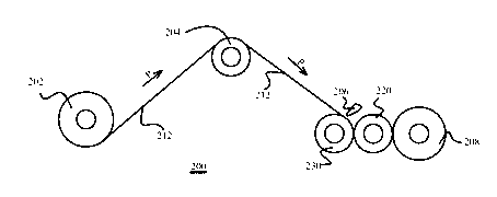
[0031] like Figure 2A As shown, it shows a schematic structural diagram of a cutting device according to an embodiment of the present invention. The cutting device 200 includes an unwinding part 202 , a pulling part 204 , a cutting part, an exhaust roller 220 and a winding roller 208 . A wide web 212, such as a plastic film with a thickness of about 0.01 to 0.15 mm and a width of about 0.5 to 2.5 m, usually in the form of a roll, is transported from the unwinding section 202 to the slitting section (such as indicated by arrow P). It should be understood that, for the sake of brevity, the traction unit 204 is only shown as one traction device. In actual operation, those skilled in the art can configure multiple traction devices in different positions according to actual needs, so as to realize wide-width coil transmission The pulling effect in the process, these multiple pulling devices can be collectively referred to as the pulling part of the present invention. In additio...
Embodiment 2
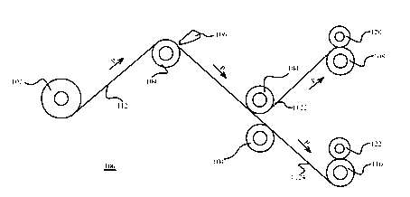
[0039] image 3 An exemplary structure of a slitting device according to another embodiment of the present invention is shown. The cutting device 300 includes an unwinding part 302 , a pulling part 304 , a cutting part, an exhaust roller 320 and a winding roller 308 . A wide web 312, such as a paper with a thickness of about 0.01 to 0.15 mm and a width of about 0.5 to 2.5 m, usually in the form of a roll, is transported from the unwinding part 302 to the slitting part via the traction part 304 (as shown by the arrow P shown). It is basically the same as the solution described in Embodiment 2, except that the wide web 312 is transported to the cutting section in the opposite direction (counterclockwise) to that shown in Embodiment 2, and the cutting section cuts it into multiple The strip, the strip is directly transported by the knife roller 330 to the exhaust roller 320 without suspended transmission, and then directly transmitted to the winding roller 308 through the exhau...
Embodiment 3
[0041] Figure 4 An exemplary structure of a slitting device according to another embodiment of the present invention is shown. The cutting device 400 includes an unwinding part 402 , a pulling part 404 , a cutting part, a winding roller 408 and an exhaust roller 420 . A wide web 412, such as a film with a thickness of about 0.01 to 0.15 mm and a width of about 0.5 to 2.5 m, usually in the form of a roll, is transported from the unwinding part 402 to the slitting part via the traction part 404 (as shown by the arrow P shown). The cutting part includes a cutting knife set 406 and a knife roller 430 . The difference from Embodiment 2 is that after the wide web 412 is transported to the cutting part, it is cut into multiple strips by the cooperation of the cutting knife group 406 and the knife roller 430, and the multiple strips are cut into strips. Transfer directly to take-up roll 408. The strip is continuously wound and pasted on the winding roller 408 without detaching fr...
PUM
| Property | Measurement | Unit |
|---|---|---|
| Width | aaaaa | aaaaa |
| Thickness | aaaaa | aaaaa |
| Width | aaaaa | aaaaa |
Abstract
Description
Claims
Application Information
 - Generate Ideas
- Intellectual Property
- Life Sciences
- Materials
- Tech Scout
- Unparalleled Data Quality
- Higher Quality Content
- 60% Fewer Hallucinations
Browse by: Latest US Patents, China's latest patents, Technical Efficacy Thesaurus, Application Domain, Technology Topic, Popular Technical Reports.
© 2025 PatSnap. All rights reserved.Legal|Privacy policy|Modern Slavery Act Transparency Statement|Sitemap|About US| Contact US: help@patsnap.com