Physically auxiliary anti-catalyst aggregated photo-catalytic reactor having high treatment capacity and used for degrading wastewater

A photocatalytic reactor and waste water degradation technology, applied in water/sewage multi-stage treatment, water/sludge/sewage treatment, chemical instruments and methods, etc. Reaction treatment device to deal with problems such as reduced efficiency

Inactive Publication Date: 2013-07-24
NINGBO UNIV
View PDF10 Cites 2 Cited by
  • Summary
  • Abstract
  • Description
  • Claims
  • Application Information

AI Technical Summary

Problems solved by technology

[0036] In the device structure expressed in the Chinese patent application with the publication number CN102260003A, the outer wall of the quartz tube used to screen the electrodeless ultraviolet lamp refers to the outer wall of the quartz tube, which is treated with the treated industrial wastewater for a long time. Contact, it is inevitable to gradually accumulate fouling. Of course, the fouling substances are mainly inorganic impurities that are not easily touched by the photocatalytic reaction. The fouling phenomenon formed by this mechanism is easy to be observed after the equipment has been running for a long time; Although the fouling layer on the outer wall of the quartz tube is only a thin layer, it is enough to significantly block the ultraviolet radiation of the electrodeless ultraviolet lamp, which will cause the actual treatment efficiency of the microwave photocatalytic

Method used


Image

  • Physically auxiliary anti-catalyst aggregated photo-catalytic reactor having high treatment capacity and used for degrading wastewater

Examples


Embodiment Construction

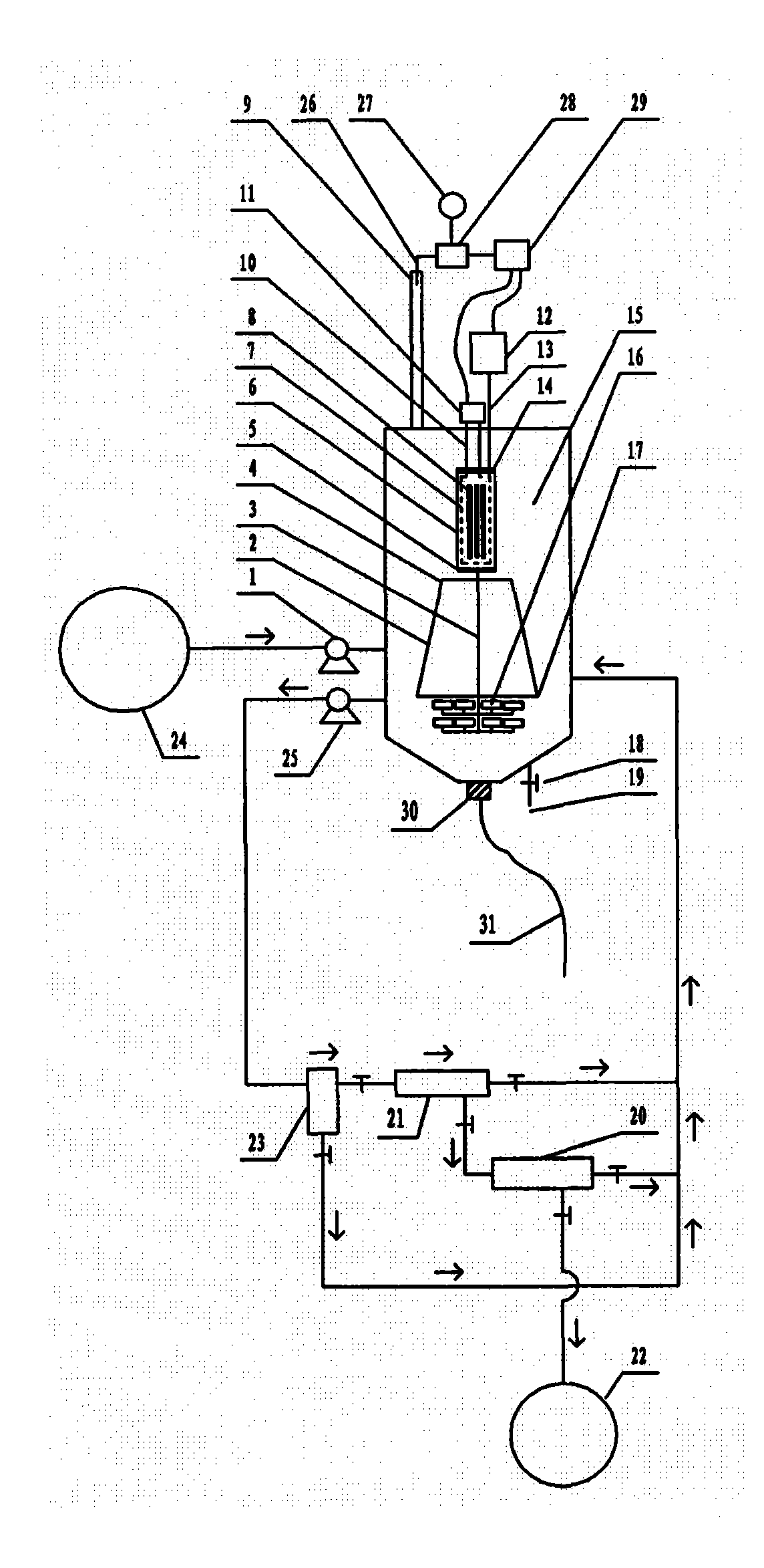
[0089] exist figure 1In the shown embodiment of the case, the structure of the reactor includes a container, and the outline of the container is in the shape of a cube, a cuboid, a cylinder, an ellipse, a polygon, a sphere or an ellipsoid. The bottom position of the inner cavity of the container is equipped with many microporous aeration heads 16, and the quartz tube 6 is installed on the inner cavity position of the container, and the two ends of the quartz tube 6 are equipped with seals. The plugging caps 5 and 14 are respectively provided with ventilation ports on the plugging caps 5 and 14 located at both ends of the quartz tube 6, and the electrodeless ultraviolet lamp 8 is rod-shaped, ring-shaped, spherical, or starfish-shaped. or sea urchin shape, the number of the electrodeless ultraviolet lamp 8 is at least one, and the number of the electrodeless ultraviolet lamp 8 is at least one above the inside of the quartz tube 6, and the air pump 12, the air pump 12 is installe...


PUM


Abstract

The invention relates to a physically auxiliary anti-catalyst aggregated photo-catalytic reactor having high treatment capacity and used for degrading wastewater, belonging to the technical field of wastewater treatment. The problems of loss of nanometer photocatalyst, waste of microwave energy, low single-tank wastewater treatment capacity of the reactor, insufficient systemic circulation intensity of internal liquid, difficulty in distinguishing a finishing point time of degradation reaction, incapability of dissipating catalyst aggregation in situ with strong force and the like exist in the current related background technology and these problems can be solved by adoption of the scheme provided by the invention. According to the invention, microwave is restrained by using a metal cage, therefore, sharp capacity expansion of the reactor is realized; the systemic circulation of internal liquid is intensified through the structure in the scheme; external cascaded three-grade back flushing type filters are beneficial to finely intercepting catalyst particles; the catalyst aggregation can be dissipated in situ with strong force through the structure; simultaneously, an ultrasonic cleaning quartz tube is incidentally arranged; related power supplies can be turned off automatically and instantly when degradation reaction is ended; energy input is stopped; simultaneously, the generation process of extra ozone is ended, therefore, secondary pollution can be avoided.

Description

technical field [0001] The invention relates to a large-capacity photocatalytic reactor for physically assisted anti-catalyst agglomeration wastewater degradation, and belongs to the technical field of CO2F wastewater treatment. Background technique [0002] Microwave photocatalytic degradation treatment technology, as an effective harmless treatment technology for industrial wastewater containing organic pollutants, has attracted much attention in recent years. [0003] Regarding the microwave photocatalytic degradation technology, as an example, refer to the Chinese patent application with publication number CN102260003A. [0004] The Chinese patent application with the publication number CN102260003A uses microwaves as the excitation source to excite the electrodeless ultraviolet lamp to emit ultraviolet rays, and irradiates the suspension mixed with photocatalyst titanium dioxide inside the liquid. The electrodeless ultraviolet lamp is shrouded and protected by a quartz ...

Claims


Application Information

Patent Timeline
IPC IPC(8): C02F9/08
Inventor 李榕生李天华任元龙葛从辛孙杰孔祖萍王冬杰张佳斌干宁
Owner NINGBO UNIV
Why Eureka
Try Eureka