Method of manufacturing chemically strengthened glass plate

A manufacturing method and glass plate technology, applied in glass manufacturing equipment, glass tempering, manufacturing tools, etc., can solve the problem of glass breaking into pieces

Inactive Publication Date: 2013-07-24
CENT GLASS CO LTD
View PDF6 Cites 16 Cited by
  • Summary
  • Abstract
  • Description
  • Claims
  • Application Information

AI Technical Summary

Problems solved by technology

If a crack for cutting the glass is formed in this tensile stress area, the crack spontaneously expands due to the tensile stress, causing the glass to break into pieces

Method used


Image

  • Method of manufacturing chemically strengthened glass plate
  • Method of manufacturing chemically strengthened glass plate

Examples


Embodiment 1

[0125] As a glass plate before ion exchange (chemical strengthening), prepare soda lime glass (by mass %, SiO 2 : 71.3%, Na 2 O: 13.0%, K 2 O: 0.85%, CaO: 9.0%, MgO: 3.6%, Al 2 o 3 : 2.0%, Fe 2 o 3 : 0.15%, SO 3 : 0.1%), prepare a disk-shaped substrate (hereinafter referred to as a glass blank) with a diameter of about 80 mm.

[0126] As the first process, the prepared glass blank is dipped in a sodium nitrate (NaNO 3 ) 100mol% molten salt (first salt, ratio X: 100mol%) bath for 2 hours.

[0127] Then, the glass blank was taken out from the bath, and the surface of the glass blank was washed and dried.

[0128] The composition of the glass base plate before and after the first step was measured by fluorescent X-rays, and it was confirmed that the ratio of sodium in the surface layer after the first step was about 1 mass % higher than the ratio of sodium in the surface layer before the first step .

[0129] Next, as a second process, the dried glass blank is immersed ...

Embodiment 2

[0139] As the second salt used in the second step, a mixed molten salt (ratio Y: 1 mol %) composed of 99 mol % of potassium nitrate and 1 mol % of sodium nitrate was prepared.

[0140] A chemically strengthened glass plate was manufactured in the same manner as in Example 1 except that the second step was performed using the above-mentioned second salt.

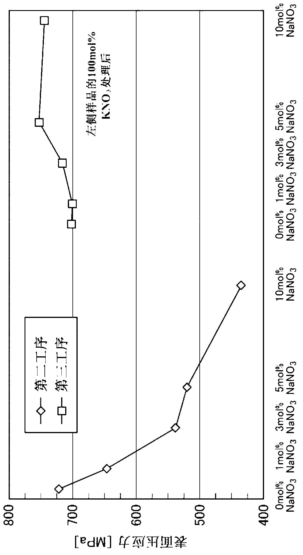
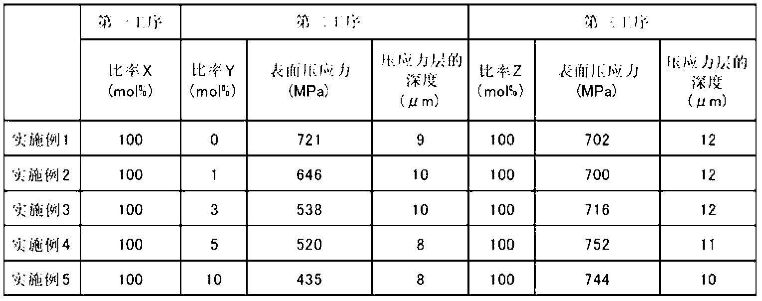
[0141] The surface compressive stress of the glass sample after the second process was 646 MPa, and the depth of the compressive stress layer was 10 μm. In addition, the surface compressive stress of the glass sample (chemically strengthened glass plate of Example 2) after the third step was 700 MPa, and the depth of the compressive stress layer was 12 μm.

Embodiment 3

[0143] As the second salt used in the second step, a mixed molten salt composed of 97 mol % of potassium nitrate and 3 mol % of sodium nitrate (ratio Y: 3 mol %) was prepared.

[0144] A chemically strengthened glass plate was manufactured in the same manner as in Example 1 except that the second step was performed using the above-mentioned second salt.

[0145] The surface compressive stress of the glass sample after the second process was 538 MPa, and the depth of the compressive stress layer was 10 μm. In addition, the surface compressive stress of the glass sample (chemically strengthened glass plate of Example 3) after the third step was 716 MPa, and the depth of the compressive stress layer was 12 μm.


PUM

PropertyMeasurementUnit
thicknessaaaaaaaaaa
depthaaaaaaaaaa
strain pointaaaaaaaaaa

Abstract

The present invention provides a method of manufacturing a chemically strengthened glass plate by ion-exchanging a glass base plate to replace alkali metal ions A that are the main alkali metal ion component of the glass base plate with alkali metal ions B having a larger ionic radius than the alkali metal ions A at a surface of the glass base plate, the unexchanged glass base plate made of a soda-lime glass, the method including: a first step of contacting the glass base plate with a first salt containing the alkali metal ions A, the first salt containing the alkali metal ions A at a ratio X, as expressed as a molar percentage of total alkali metal ions, of 90 to 100 mol %; a second step of contacting the glass plate with a second salt containing the alkali metal ions B after the first step, the second salt containing the alkali metal ions A at a ratio Y, as expressed as a molar percentage of the total alkali metal ions, of 0 to 10 mol %; and a third step of contacting the glass plate with a third salt containing the alkali metal ions B after the second step, the third salt containing the alkali metal ions B at a ratio Z, as expressed as a molar percentage of the total alkali metal ions, of 98 to 100 mol %.

Description

technical field [0001] The present invention relates to a method for manufacturing a chemically strengthened glass plate, and more specifically, to a cover glass suitable for mounting in a display unit (including a case that also includes an input unit) of an electronic device typified by a mobile phone, a smartphone, or a tablet computer Or a method of manufacturing a chemically strengthened glass plate of an integrated cover glass having both substrate and cover functions. Background technique [0002] Resin covers are widely used as protective materials for displays of portable electronic devices such as mobile phones and smartphones. However, the demand for glass as a protective material for displays has increased in recent years due to its superior transmittance, weather resistance, or scratch resistance compared to resin covers, or for the purpose of improving the appearance of displays. Taller. Furthermore, in order to meet the requirements for light weight and thin...

Claims


Application Information

Patent Timeline
Patent Type & Authority Applications(China)
IPC IPC(8): C03B27/03
CPCC03C21/002
Inventor 长谷川聪都筑达也村本正三田村直树松田裕
Owner CENT GLASS CO LTD
Why Eureka
Try Eureka