

Fiberglass-reinforced plastics (FRP) section bar buckling-resisting supporting structure
A technology of anti-buckling bracing and profiles, applied in earthquake-proofing, building components and other directions, can solve the problems of limiting the popularization and application of anti-buckling bracing, self-heavy, slow construction, etc., to facilitate large-scale industrialized rapid production, high production efficiency, and improve seismic performance effect
- Summary
- Abstract
- Description
- Claims
- Application Information
AI Technical Summary
Problems solved by technology
Method used
Image

Examples
Embodiment 1
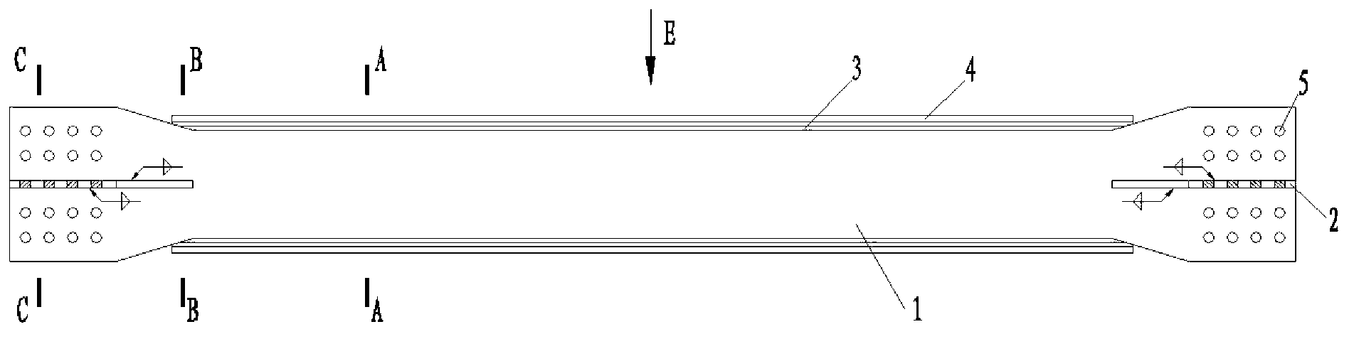
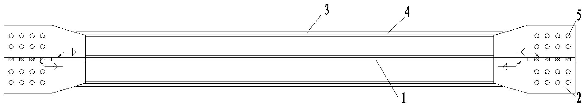
[0029] Such as figure 1 , figure 2 The fast industrialized production of the FRP profile anti-buckling support of the present invention includes an inline steel plate 1 as the inner core, a new steel plate 2 at the end, FRP hollow ribbed profile 3 and FRP cloth 4 as the outer core. The straight steel plate 1 is vertically welded to the steel plate 2 at both ends to form a cross shape, which is convenient for connecting with structural components. Clamp two FRP hollow ribbed profiles 3 on both sides of the in-line steel plate 1, wrap FRP fabric 4 around the outer ring, and fill the space between the in-line steel plate 1, the FRP hollow ribbed profile 3 and the FRP fabric 4 with porous foam material . The end of the inline steel plate 1 and the steel plate 2 can be provided with a connection structure for connecting with the structure, which is a through hole 5 in this example.
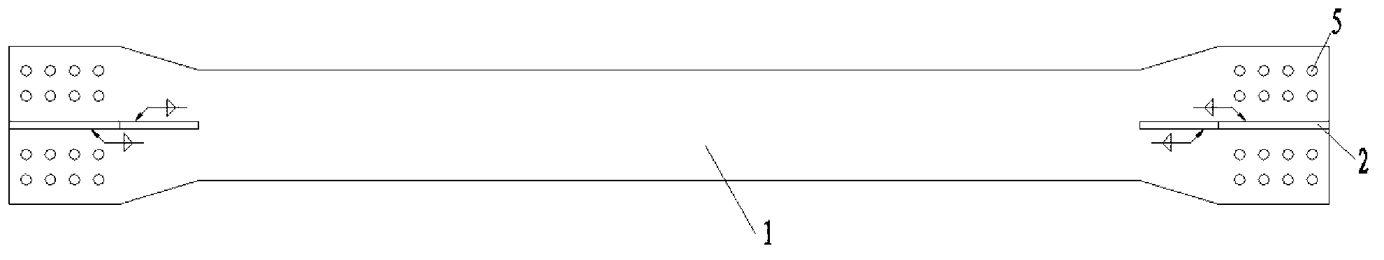
[0030] Such as image 3 As shown, the middle part of the inline steel plate 1 is respectively ...
Embodiment 2
[0034] see Figure 8 , the difference from Embodiment 1 is that two structures 8 according to the invention are arranged in one span. At this time, it is necessary to install an embedded panel 11 in the middle of the frame beam, and if necessary, a stiffener needs to be added on the embedded panel 11 to ensure the connection strength and rigidity.
PUM
 Abstract
Description
Claims
Application Information