Coupling device, cavity filter and communication radio frequency equipment

A technology of coupling device and coupling body, which is applied in the direction of connection devices, waveguide devices, electrical components, etc., can solve the problems of glue safety hazards, falling into the cavity, and inconvenient production, so as to achieve improved safety, high safety, The effect of easy installation

Active Publication Date: 2013-07-24
ANHUI TATFOOK TECH CO LTD
View PDF3 Cites 9 Cited by
  • Summary
  • Abstract
  • Description
  • Claims
  • Application Information

AI Technical Summary

Problems solved by technology

[0005] 1. The adjustment mechanism is not an integral part. Due to the small size of these components, it is easy for the debugger to fall off the components and fall into the cavity during the assembly process, resulting in waste of time and inconvenience in production;
[0006] 2. Unlimited position function, when the debugging components enter a lot and are very close to the signal transmission body, it may cause a short circuit
[0007] 3. There is no self-locking function, and the existing coupling device needs to be fixed by dispensing glue, and there are certain safety hazards in the process of high and low temperature glue

Method used


Image

  • Coupling device, cavity filter and communication radio frequency equipment
  • Coupling device, cavity filter and communication radio frequency equipment
  • Coupling device, cavity filter and communication radio frequency equipment

Examples


Embodiment 1

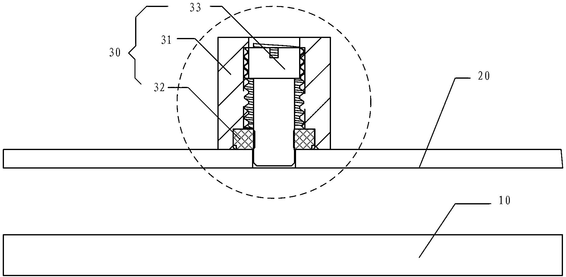
[0021] Example one, as figure 1 As shown, the present invention provides a communication radio frequency device, which can be a cavity filter, a simplexer, a duplexer, a multiplexer, a combiner or a splitter, and the communication radio frequency device includes a signal transmission body 10, a circuit The board 20 and the coupling device 30. The coupling device 30 is mounted on the circuit board 20 and is used for coupling the signal of the coupled signal transmission body 10 to the circuit board 20. The coupling device 30 includes:

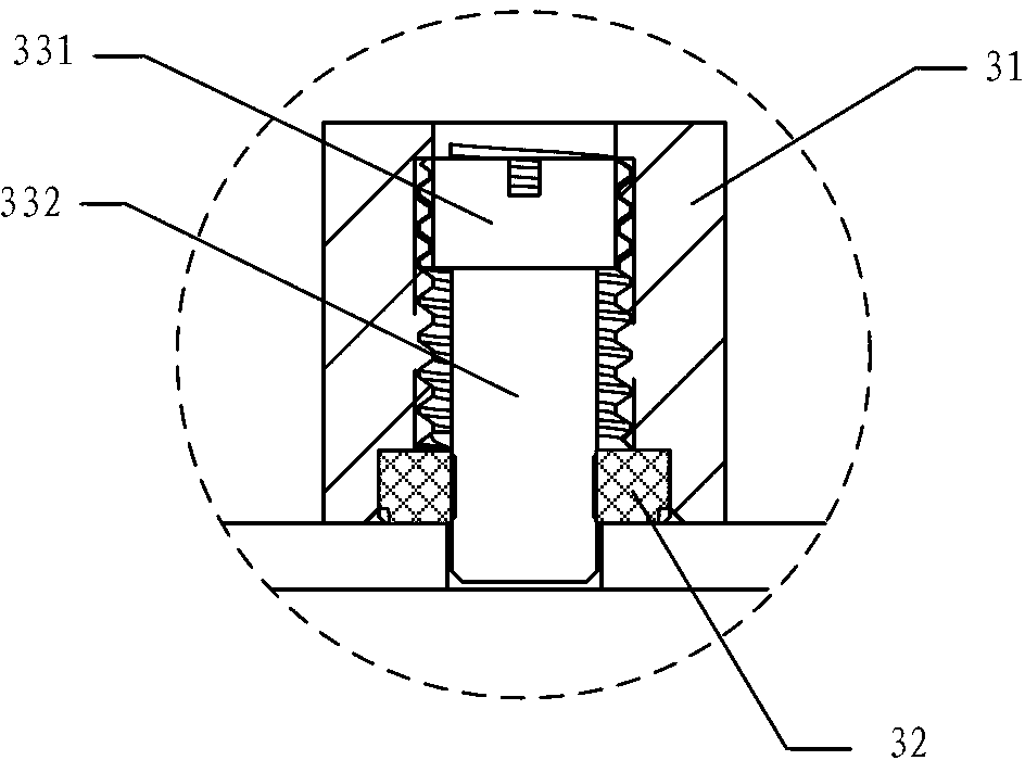
[0022] The coupling outer conductor 31 is provided with a through hole, the middle of the through hole is threaded and one end of the through hole is provided with a countersunk hole, while the other end of the through hole is not provided with a thread, and one end of the coupling outer conductor 31 has a countersunk hole and the circuit board 20 is connected, and the circuit board 20 is provided with through holes corresponding to the through ...

Embodiment 2

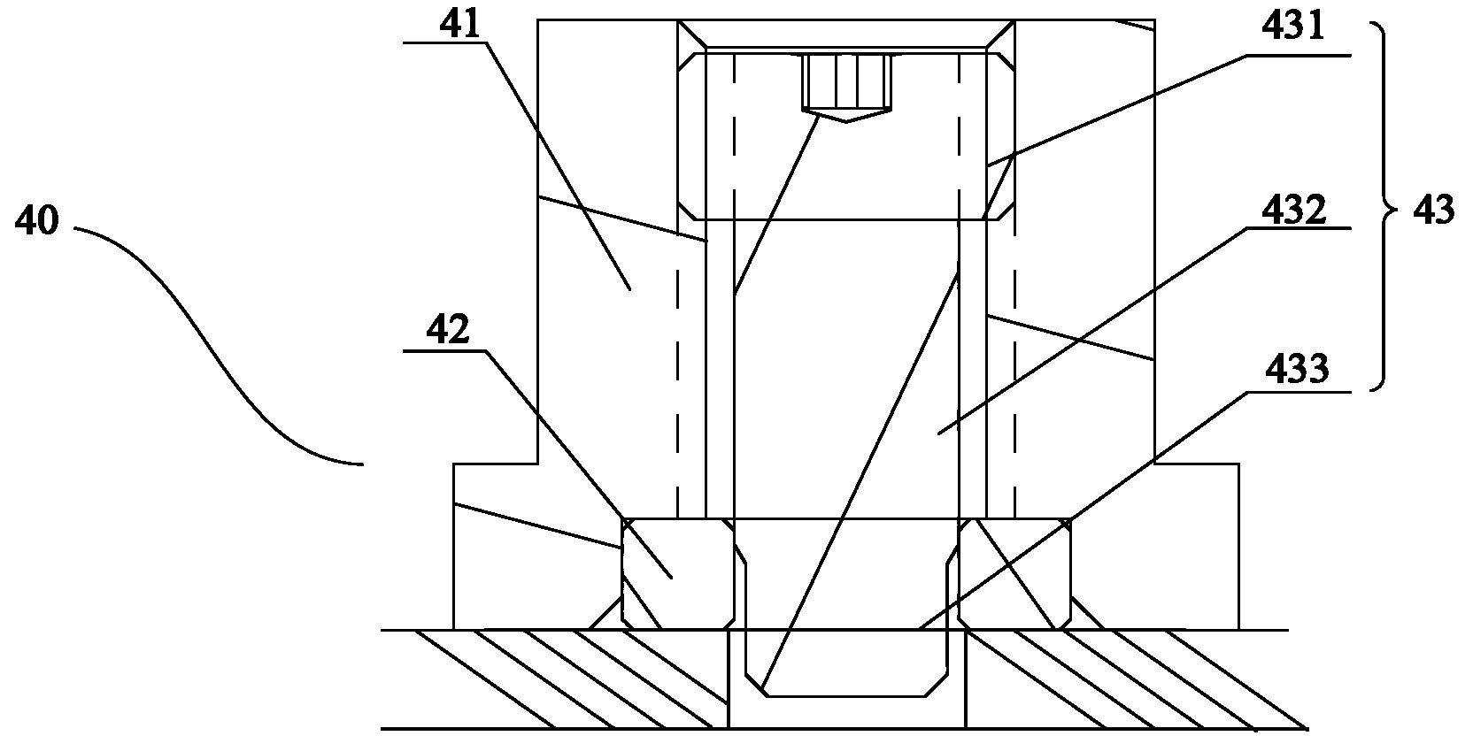
[0032] In this embodiment, the coupling inner conductor and the elastic fixing block in the coupling outer conductor are arranged in an interference fit close to the end of the printed circuit board, and the coupling inner conductor and the coupling outer conductor are threadedly arranged in an end far away from the printed circuit board.

[0033] Specifically, the through hole in the coupling outer conductor includes a first segment hole close to the printed circuit board end and a second segment hole away from the printed circuit board end, the elastic fixing block is accommodated in the first segment hole, and the coupling inner conductor and the elastic fixing block Interference fit and thread fit with the second hole, the diameter of the first hole is larger than that of the second hole.

[0034] refer to image 3 The coupling body 40 includes a coupling outer conductor 41, a coupling inner conductor 43, and an elastic fixing block 42. The coupling inner conductor in the ...

Embodiment 3

[0042] In this embodiment, the coupling inner conductor and the elastic fixing block in the coupling outer conductor are arranged in an interference fit at the end away from the printed circuit board, and the coupling inner conductor and the coupling outer conductor are threaded and arranged at the end close to the printed circuit board.

[0043] Specifically, refer to Figure 5 , Figure 5 It is a schematic cross-sectional view of the coupling body 60. The through holes in the coupling outer conductor 61 include a first segment hole near the printed circuit board end and a second segment hole away from the printed circuit board end. The elastic fixing block 62 is arranged in the second segment hole, coupling The 632 of the inner conductor 63 close to the end of the printed circuit board is threadedly matched with the first section hole of the coupling outer conductor 61, and is interference fit with the elastic fixing block 62 arranged in the second section hole through 631. ...


PUM


Abstract

The invention discloses a coupling device, a cavity filter and communication radio frequency equipment. The coupling device comprises a signal transmission main rod and a coupling body which is used for acquiring a signal of the signal transmission main rod, wherein the coupling body is connected to a printed circuit board in parallel to the signal transmission main rod. The coupling device is characterized in that the coupling body comprises a coupling outer conductor which is connected to the printed circuit board, and a coupling inner conductor which is arranged in the coupling outer conductor, wherein one end of the coupling inner conductor is positioned in a through hole of the printed circuit board; the coupling inner conductor comprises a threaded part and is in threaded fit with the coupling outer conductor through the threaded part; an elastic fixing block is arranged between the coupling outer conductor and the coupling inner conductor; and the coupling inner conductor is in interference fit with the elastic fixing block and is fixed in the through hole of the coupling outer conductor. The coupling device can be conveniently installed, has limiting and self-locking functions, is free of short-circuit, and is high in safety.

Description

technical field [0001] The invention relates to a coupling device, a cavity filter and a communication radio frequency device. Background technique [0002] As a frequency selective device, cavity filters are widely used in the field of communication, especially in the field of radio frequency communication. In the base station, the cavity filter is used to select the communication signal and filter out the clutter or interference signal other than the frequency of the communication signal. In the cavity filter, it is often necessary to divide one microwave power into several channels in proportion, and the module that realizes this function is called a power distribution module, that is, a coupling module. [0003] The coupling module is a four-port module with directional transmission characteristics. It distributes the power of the microwave signal according to a certain ratio. It can be used for signal isolation, separation and mixing, and power signal sampling, which i...

Claims


Application Information

Patent Timeline
Patent Type & Authority Applications(China)
IPC IPC(8): H01P5/00H01P1/207
Inventor 王义参吴文敬刘锡垣
Owner ANHUI TATFOOK TECH CO LTD
Why Eureka
Try Eureka