
Method for automatic hydraulic compensation in fluid-onducting systems

An automatic and hydraulic technology, applied in the direction of mechanical equipment, heat exchange equipment, lighting and heating equipment, etc., can solve the problems of ignorance of pipe guidance control, insufficient pipeline regulating valves, and impossible static adjustment, etc., to reduce energy consumption , small pressure loss, and the effect of reducing flow noise

Inactive Publication Date: 2013-07-24
F W OVENTROP KG
View PDF5 Cites 4 Cited by
  • Summary
  • Abstract
  • Description
  • Claims
  • Application Information

AI Technical Summary

Problems solved by technology

Previously simple static flow adjustments, e.g. via line control valves in plants where load conditions vary frequently, are not sufficient
Furthermore, above all in older installations, the actual control of the tube guidance is often not known and even an optimal static adjustment is not possible

Method used


Image

  • Method for automatic hydraulic compensation in fluid-onducting systems
  • Method for automatic hydraulic compensation in fluid-onducting systems
  • Method for automatic hydraulic compensation in fluid-onducting systems

Examples


Embodiment Construction

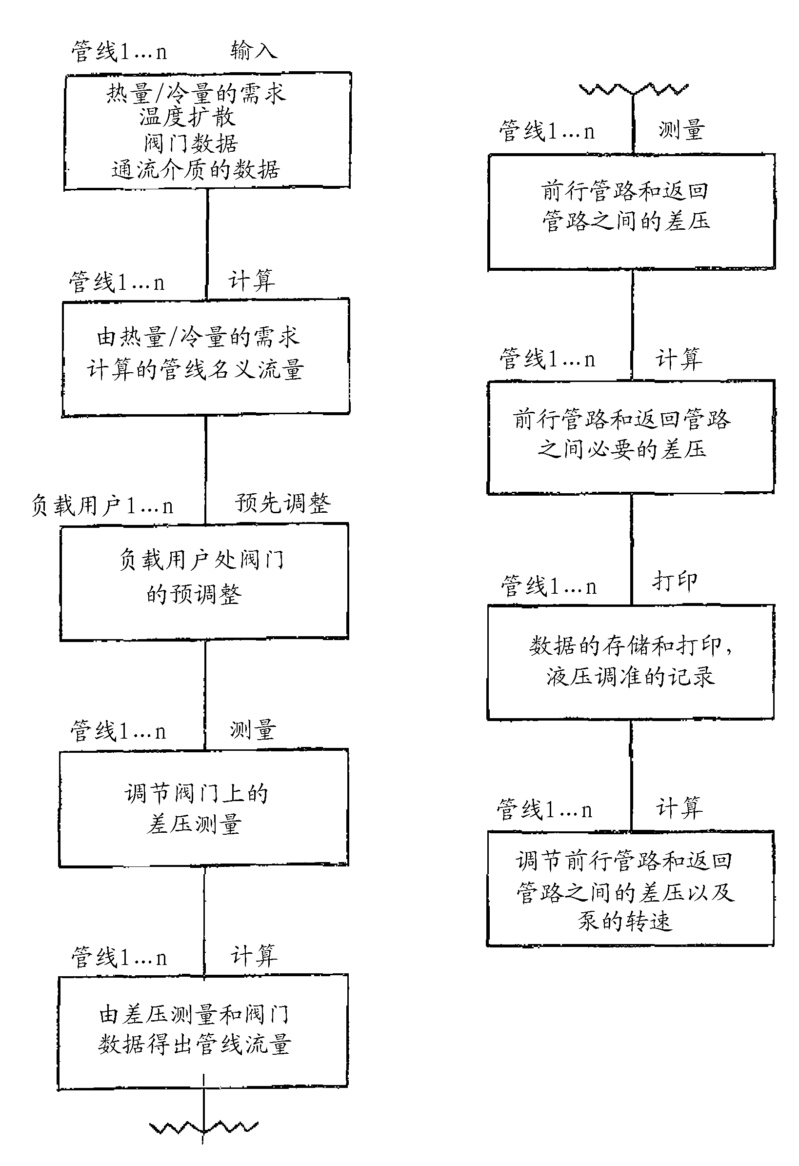
[0021] As shown in FIG. 3 , in the method according to the invention the plant parameters are first entered, read into a computing unit and stored therein.

[0022] For each line 1 to n, for example, heat / cooling requirements, temperature spread, valve data and parameters of the flow medium are entered. Then for each line 1 to n, the calculation of the nominal flow of the line is performed from the calculation of the heating / cooling demand. In addition, a presetting is carried out for each load subscriber 1 to n, that is to say the valves on the respective load subscriber are preadjusted. In addition for each line 1 to n a differential pressure measurement is carried out at the regulating valve. Calculations of line flow are then made from differential pressure measurements and valve data. These data are read and stored in the computing unit. In the case of a truly permanent dynamic hydraulic adjustment of the plant, a measurement of the line differential pressure between t...


PUM


Abstract

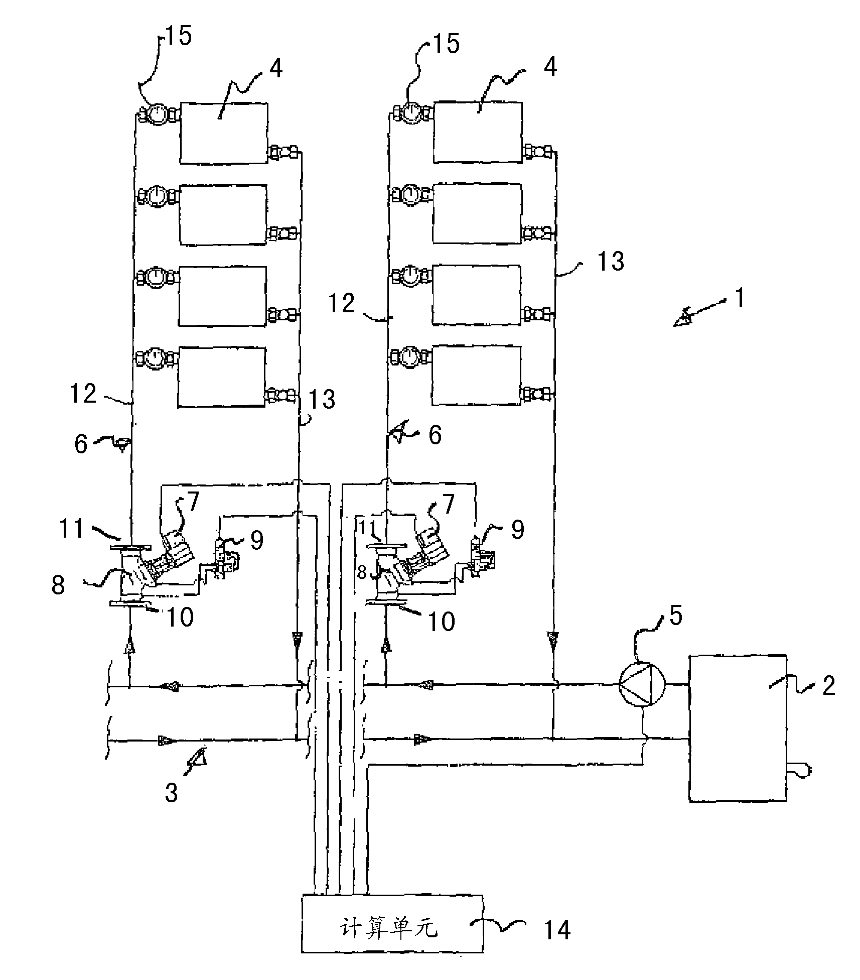
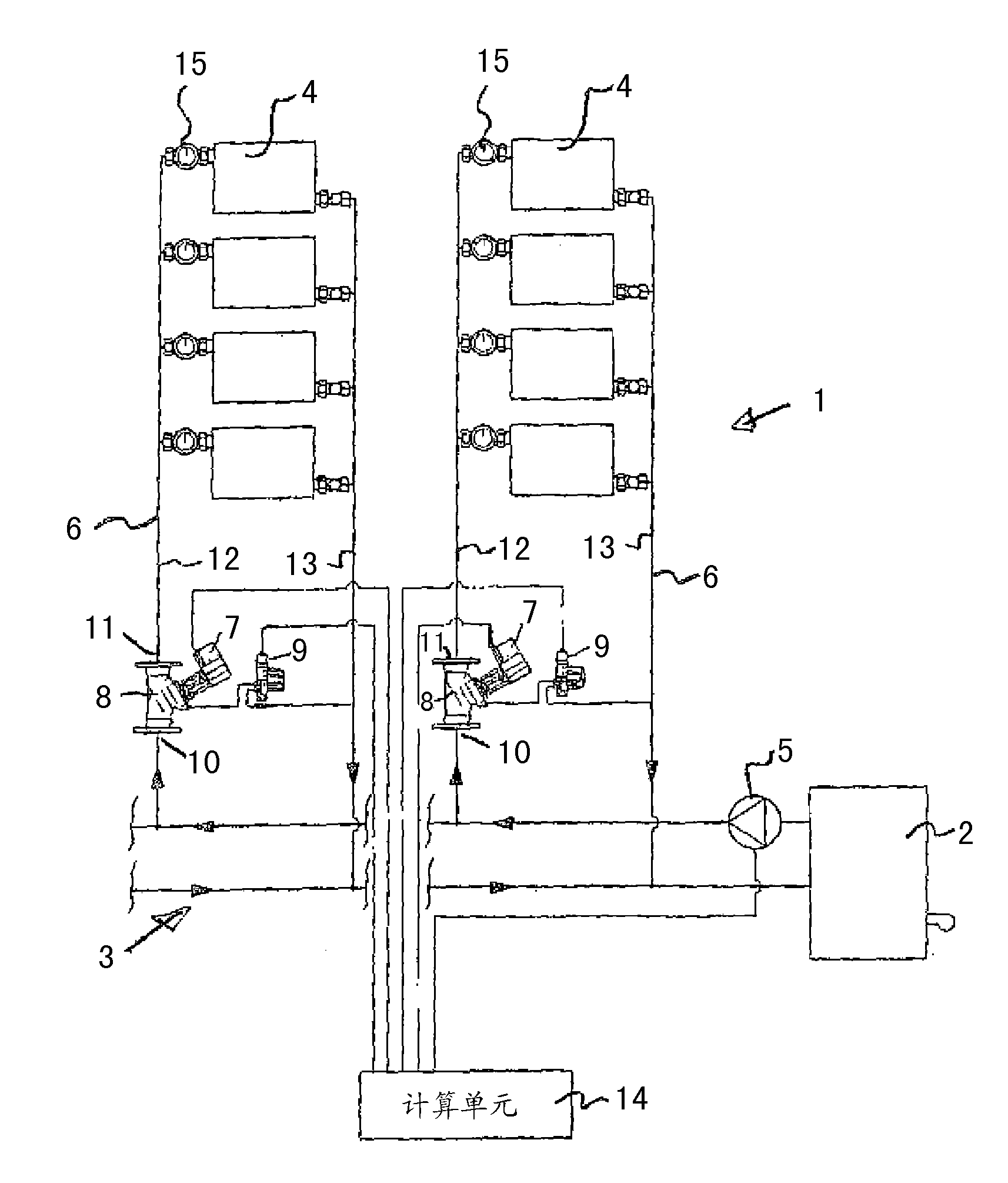
The invention relates to a method for automatic hydraulic compensation of heating and / or cooling systems (1) having a heat and / or cold producer (2), a plurality of loads (4) connected in strands, and a circulating pump (5), wherein control valves (8) provided with actuating drives (7) are installed in the pipeline strands (6) in order to control the strand differential pressures, wherein in a first method step the differential pressures of the inlet side (10) and outlet side (11) of the control valves (8) are detected and subsequently the strand differential pressures between the feed line (12) and the return line (13) are detected by one differential pressure sensor (9) per pipeline strand (6) and the detected measured data are read into a computing unit (14) and are stored in said computing unit, and in a second method step the strand differential pressures in all pipeline strands (6); are continuously measured, the measured data are transferred to the computing unit (14) and compared with the stored data pattern, wherein actuating commands are generated from the determined comparison data by the computing unit (14). The current strand differential pressures are controlled to the stored target differential pressures by the actuating drives (7) of the control valves (8) by means of said actuating commands.

Description

technical field [0001] The invention relates to a method for automatic hydraulic alignment of heating- and / or cooling installations, through which a heat-transfer medium flows, with at least one heating- and / or refrigerating device, several of which carry heat through a conduction The overall piping system is line-like connected load users, and has at least one circulation pump, wherein a control valve with a servo drive is arranged in the line for adjusting the line differential pressure. Background technique [0002] The heat transfer medium is a fluid, preferably water. The method can be applied to systems with at least one heating- and / or cooling unit, several load customers, lines for conducting liquid connections between heating- and / or cooling units and load customers, and at least one circuit Pumps and heating- and / or cooling devices with regulating valves incorporated in the lines. [0003] Due to the ever-increasing demands placed on the energy saving of fluid-co...

Claims


Application Information

Patent Timeline
Patent Type & Authority Applications(China)
IPC IPC(8): F24D19/10
CPCF24F11/008Y02B30/745F24D19/10F24D19/1036F24F3/06F24D19/1012F24D2220/0264F28F27/00F24F11/83Y02B30/70F24F11/85F24F11/84
Inventor G.勒夫勒
Owner F W OVENTROP KG
Learn More