Vacuum heat collection element with middle piece pressure-reducing air drying protector

A heat-collecting element and vacuum heat-collecting technology, which is applied to solar collectors, solar collectors, heating devices and other directions using working fluids, which can solve the problem that the accuracy cannot work normally and effectively. The problems of poor consistency of the chip thermal transducer driver and reduced ability to restore the original state can achieve the effects of improving reliability, reducing heat dissipation power, and reducing outgassing.

Active Publication Date: 2013-07-31
唐山图灵科技股份有限公司
View PDF3 Cites 0 Cited by
  • Summary
  • Abstract
  • Description
  • Claims
  • Application Information

AI Technical Summary

Problems solved by technology

Since this patent is not specifically aimed at the heat-collecting elements of gravity heat pipes, it is not very targeted; the bimetal sheet thermal energy conversion drive used in it is originally not consistent with the product, and has the ability to return to its original shape after repeated heat deformation It will be reduced again, and the operating point setting, control variable input, comparison, energy conversion and energy supply and execution functions related to the control system undertaken by it are far from being able to work normally and effectively due to the impact on the accuracy of the possible 20-year design of the heat collecting element. life

Method used


Image

  • Vacuum heat collection element with middle piece pressure-reducing air drying protector
  • Vacuum heat collection element with middle piece pressure-reducing air drying protector
  • Vacuum heat collection element with middle piece pressure-reducing air drying protector

Examples


Embodiment Construction

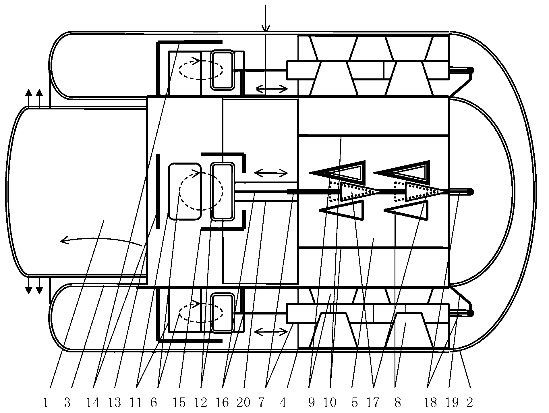
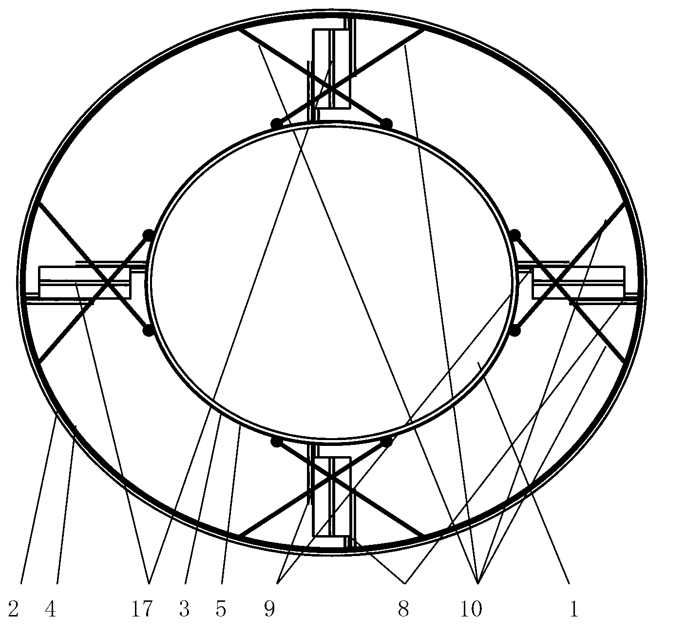
[0031] figure 1 with figure 2 An example of the present invention is given.

[0032] figure 1 with figure 2 In the vacuum insulation layer between the end of the glass tube 2 and the end of the inner glass tube 3 of an all-glass vacuum heat collecting tube, four medium-sheet vacuum heat pipes are evenly distributed along the circumference of the annular vacuum heat insulation layer. The components are decompressed and air-dried to protect the heat transfer channel. It is composed of a vacuum heat-collecting element with a middle-piece decompression air-sun protector. The air-sun protection heat transfer channel is composed of a heat dissipation patch 4, a heat sink 5, a thermal drive device 6, and a middle plate 7 connected to the thermal drive device 6 in transmission. The shape of the outer surface of the heat dissipation patch 4 matches the shape of the inner surface of the rounded end of the cover glass tube 2 and contains an inwardly-flanged punching hole 8. The heat...


PUM


Abstract

A vacuum heat collection element with a middle piece pressure-reducing air drying protector is formed by arranging a middle piece pressure-reducing air drying protector in a vacuum thermal insulating layer between the tail end of a shade glass tube of a full-glass vacuum heat collection pipe and the tail end of an inner glass tube, wherein the middle piece pressure-reducing air drying protector comprises more than one air drying protection heat transmission channel; the air drying protective heat transmission channel comprises a heat dissipation paster, a heat sink, a heat power driving component with an interface in heat transmission connection with the inner glass tube, and a middle piece rotationally connected with or produced integrally with the heat power driving component; the air drying protection heat transmission channel has two stable states, namely an open heat conduction state in which the middle piece is in heat transmission connection with the heat sink and the heat dissipation paster simultaneously, and a close heat insulation state in which the middle piece is not in heat transmission connection with the heat dissipation paster and the heat sink simultaneously. The vacuum heat collection element is characterized in that the heat dissipation paster comprises a low thermal resistance connection interface connected with the shade glass tube round end inner surface, and a heat transmission interface connected with the middle piece. The element ensures that the pressure of a 70-watt heat collection element does not surpass 2 barometric pressures by using 10-watt heat dissipation power, and is high in reliability.

Description

Technical field [0001] The invention relates to a vacuum heat collecting element with a middle-piece decompression air-sun protector. Background technique [0002] The vacuum heat collecting tube is provided with a vacuum insulation layer between the cover glass tube and the inner glass tube, which can be used to manufacture vacuum solar water heaters that can provide domestic hot water in winter. Solar water heaters made of heat pipe vacuum collector tubes have the advantages of high energy efficiency ratio without water in the tube, compliance with sanitary drinking water standards, and single tube damage. therefore. Solar vacuum heat pipe water heaters without water inside the tube will likely occupy more and more market shares. [0003] The use of an integrated glass heat pipe has the advantages of being able to be fused with the cover glass pipe, the surface of the glass heat pipe can be directly made of an absorption film, and there are few heat transfer links, and the wat...

Claims


Application Information

Patent Timeline
Patent Type & Authority Applications(China)
IPC IPC(8): F24J2/05F24J2/32F24J2/46F24S10/40F24S10/95
CPCY02E10/44
Inventor 施国樑
Owner 唐山图灵科技股份有限公司
Why Eureka
Try Eureka