
Startup and shutdown circuit

A switching circuit and switching technology, applied in computer control, instruments, simulators, etc., can solve problems such as power loss, file system damage, and excessive standby current.

Active Publication Date: 2013-07-31
SHENZHEN COMEN MEDICAL INSTR
View PDF7 Cites 18 Cited by
  • Summary
  • Abstract
  • Description
  • Claims
  • Application Information

AI Technical Summary

Problems solved by technology

[0003] The way of hardware switch is to turn on or off the power of the control system by pressing and disconnecting the power button. The advantage is that the principle is very simple to realize. : When the power switch is turned off, the system power will be turned off immediately, and the configuration data of the monitor cannot be stored by some users. If the key is pressed when the microprocessor is processing key programs or storing key data, the system power will be turned off. It is easy to cause loss of important data and damage to the file system
[0004] In order to save the user configuration data of the monitor, avoid the loss of important data and the damage of the file system, the current multi-parameter monitor basically adopts the method of software shutdown to control the power on and off of the system. The MCU of the machine button continues to supply power. When the power button is detected, it will be turned on again. When the power button is pressed, the multi-parameter monitor can be delayed by the software to store the user's configuration data, after processing key programs or storing key data. , Shut down by software, which increases the stability of the system. The disadvantage is that the standby current is too large, and there is power loss at the milliamp (mA) level.

Method used

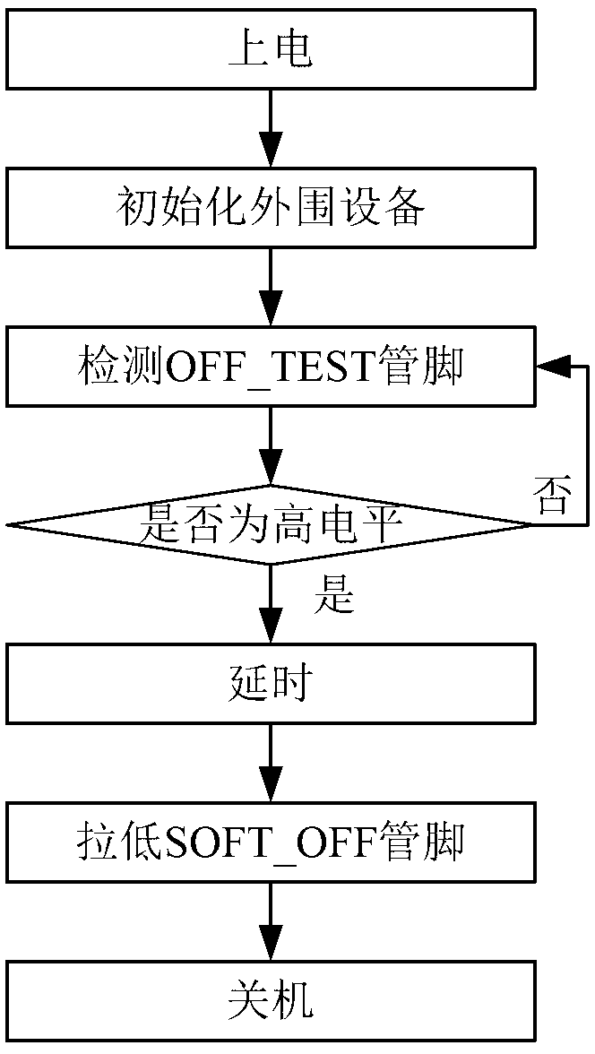

Image

  • Startup and shutdown circuit
  • Startup and shutdown circuit
  • Startup and shutdown circuit

Examples


Embodiment Construction

[0021] The specific implementation manners of the present invention will be described in detail below in conjunction with the accompanying drawings.

[0022] One embodiment of the present invention is the switch machine circuit, which is characterized in that it includes a power-on button, a power-on delay circuit, a power-on buffer circuit, a power-on / off enabling circuit, a power supply circuit, a power-on level locking circuit, a power-off detection circuit, and a single-chip microcomputer control circuit. Circuit; For example, the present invention is mainly made up of power button, startup delay circuit, shutdown button, shutdown detection circuit, startup level locking circuit, startup buffer circuit, switch enabling circuit, single-chip microcomputer control circuit and single-chip microcomputer control software.

[0023] A block diagram of an embodiment such as figure 1 As shown, the power-on button, the power-on delay circuit, the power-on buffer circuit, and the powe...


PUM


Abstract

The invention relates to a startup and shutdown circuit which comprises a startup key, a startup delay circuit, a startup buffer circuit, a startup and shutdown enabling circuit, a power circuit, a startup level locking circuit, a shutdown detection circuit and a singlechip control circuit, wherein the startup key, the startup delay circuit, the startup buffer circuit and the startup and shutdown enabling circuit are sequentially connected; the startup and shutdown enabling circuit is connected with the power circuit; the power circuit, the startup level locking circuit and the startup delay circuit are sequentially connected; the power circuit is further connected with the startup buffer circuit; and the shutdown detection circuit, the singlechip control circuit and the startup and shutdown enabling circuit are sequentially connected. The startup and shutdown circuit is applicable to a multi-parameter monitor, improves the system stability through hardware startup and software shutdown, has the advantages of simplicity, stability, low standby current, low energy consumption, flexible design and the like, and greatly improves a use effect of a user.

Description

【Technical field】 [0001] The invention relates to the way of hardware startup and software shutdown of an instrument, in particular to a switch circuit. 【Background technique】 [0002] At present, in the application of medical equipment, there are mainly two ways to design the switch machine circuit, one is to control the switch machine by hardware, and the other is to control the switch machine by software. [0003] The way of hardware switch is to turn on or off the power of the control system by pressing and disconnecting the power button. The advantage is that the principle is very simple to realize. : When the power switch is turned off, the system power will be turned off immediately, and the configuration data of the monitor cannot be stored by some users. If the key is pressed when the microprocessor is processing key programs or storing key data, the system power will be turned off. It is easy to cause loss of important data and damage to the file system. [0004]...

Claims


Application Information

Patent Timeline
IPC IPC(8): G05B19/042
Inventor 尹鹏李尔松邹海涛
Owner SHENZHEN COMEN MEDICAL INSTR
Learn More