Differential current sensor

A differential current and sensor technology, applied in the direction of measuring current/voltage, parts and instruments of electrical measuring instruments, etc., can solve the problems of impossible calibration and connection, and achieve the effect of preventing temperature difference and improving the accuracy of measurement

Inactive Publication Date: 2013-07-31
ISABELLENHUTTE HEUSLER
View PDF11 Cites 8 Cited by
  • Summary
  • Abstract
  • Description
  • Claims
  • Application Information

AI Technical Summary

Problems solved by technology

However, the measurement transducer itself always measures the voltage drop across the current sense resistor and cannot be connected to a reference voltage
A full calibration is not possible in this way

Method used


Image

  • Differential current sensor
  • Differential current sensor
  • Differential current sensor

Examples


Embodiment Construction

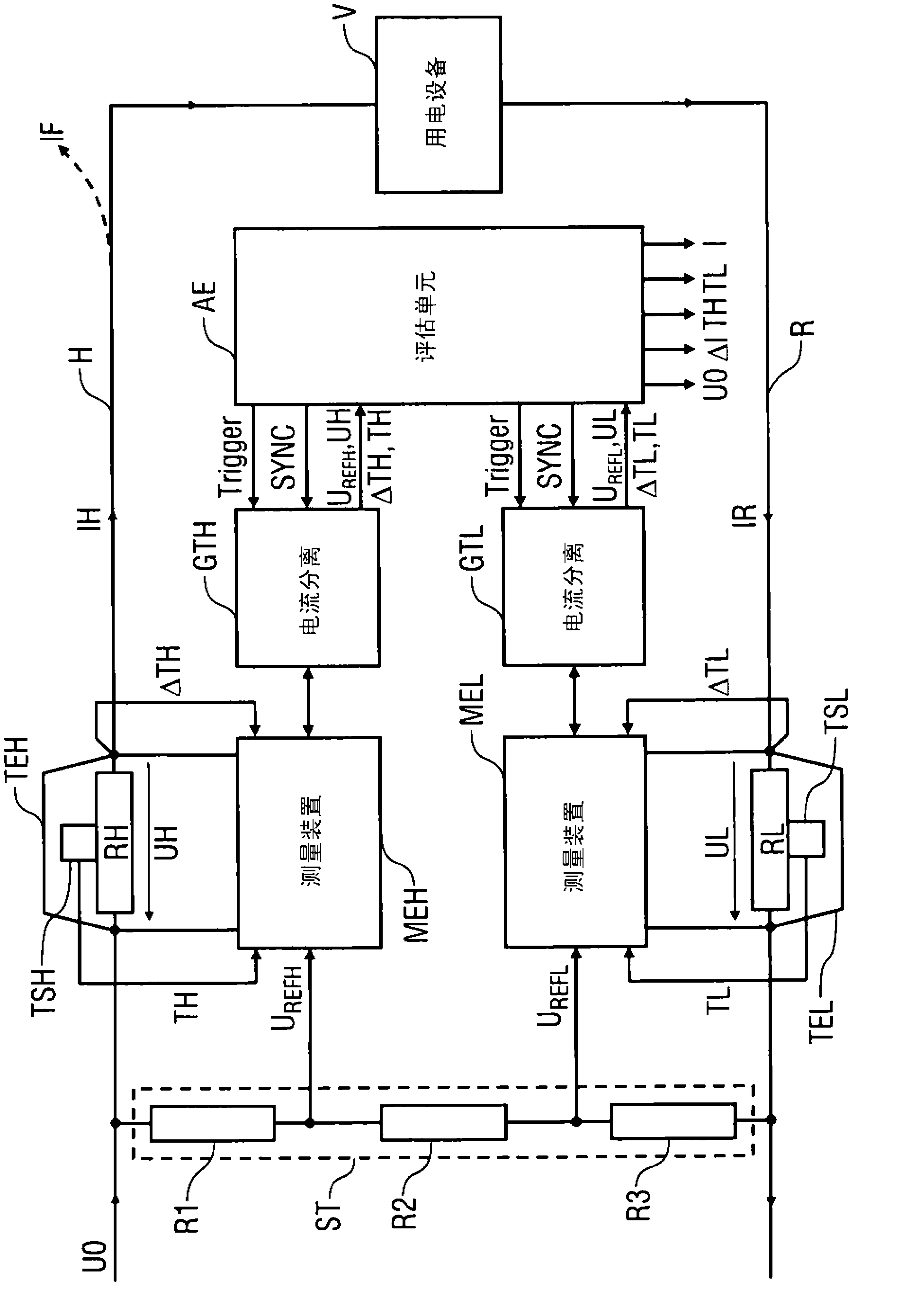
[0030] The drawing shows a schematic diagram of a differential current sensor according to the invention, which can be used, for example, in a single-phase DC power supply network in order to measure the differential current ΔI.

[0031]The DC power supply network is only schematically shown here. In essence, the DC power supply network is composed of a transmission wire H, a loop wire R and a schematically shown electrical device V, wherein the current IH flows through the transmission wire H to reach the user The electrical equipment V, while the corresponding current IR flows back through the loop wire R.

[0032] In the case of fault-free operation, the current IH through the supply conductor H corresponds exactly to the current IR through the return conductor R.

[0033] In the event of a fault, however, for example in the event of a short circuit to ground or a leakage current to ground, a fault current IR may flow away from the feed conductor H. In the event of such a ...


PUM


Abstract

The invention relates to a differential current sensor for measuring the differential current ([delta] I) between an electric current (IH) flowing through a feed conductor (H) and an electric current (IR) flowing through a return conductor (R), said sensor comprising: two low-resistance current measuring resistors (RH, RL) for measuring the currents (IH, IR) in the feed conductor (H) and the return conductor (R); two measuring devices (MEH, MEL), each of which has a transducer for measuring the current drops (UH, UL) across the two current measuring resistors (RH, RL); and two voltage references (UREFH, UREFL) for calibrating the measuring devices (MEH, MEL). According to the invention, the two transducers measure in succession both the voltage drop (UH) across their respective current measuring resistor (RH) and the associated voltage references (UREFH, UREFL).

Description

technical field [0001] The invention relates to a differential current sensor, especially a DC power supply system. Background technique [0002] A differential current sensor of this type is known from WO 00 / 00834 A1, which can be used, for example, in single-phase AC power supply systems in order to measure the current in the feed and return conductors, from which the differential current so that faults can be detected. Here, the actual current measurement is carried out according to the per se known four-wire technology by means of low-resistance current-sensing resistors arranged respectively in the supply and return conductors, through which the current to be measured flows , such that the voltage drop across the current sense resistor forms a measure of the corresponding current. This known differential current sensor also has an ASIC (ASIC: Application Specific Integrated Circuit), which calculates the voltage across the two current-sensing resistors in the supply a...

Claims


Application Information

Patent Timeline
Patent Type & Authority Applications(China)
IPC IPC(8): G01R1/20G01R19/25
CPCG01R1/203G01R19/10G01R19/2506G01R1/20G01R19/25
Inventor U·黑茨勒
Owner ISABELLENHUTTE HEUSLER
Why Eureka
Try Eureka