

Luminous anti-puncture labor insurance boot with self-generated power source
A technology for puncture-proof and labor protection boots, which is applied to boot legs, shoe uppers, clothing, etc. It can solve the problems of not being able to see the position of the feet, easily damaging the opponent's feet, and inconvenient wearing and walking, and achieves a good puncture-proof effect , good adhesion performance, and the effect of reducing weight
- Summary
- Abstract
- Description
- Claims
- Application Information
AI Technical Summary
Problems solved by technology
Method used
Image

Examples
Embodiment 1
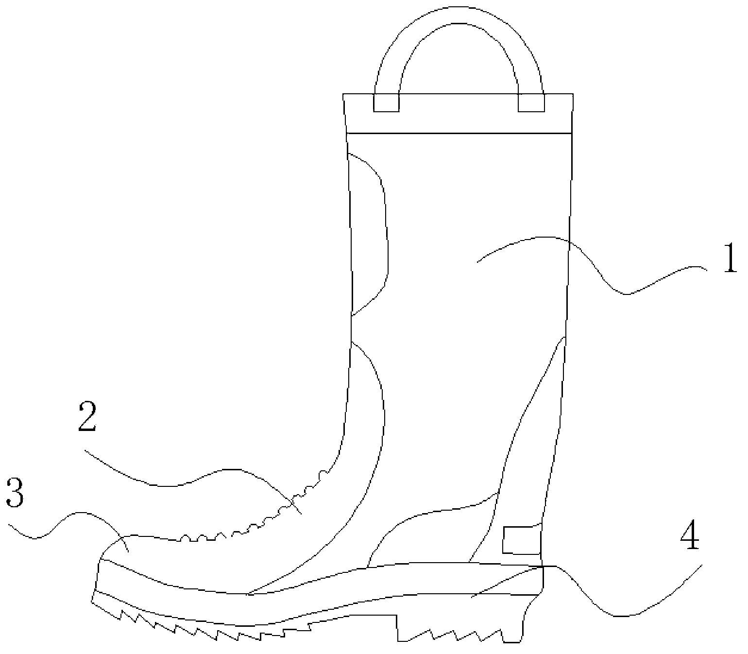
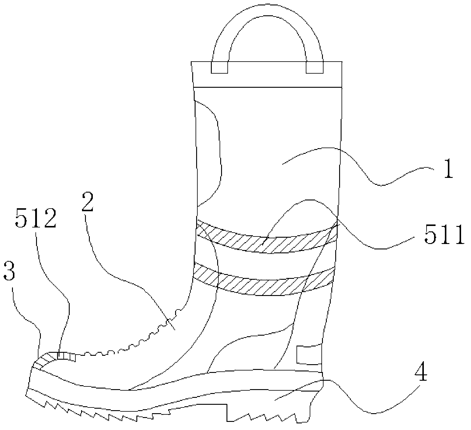
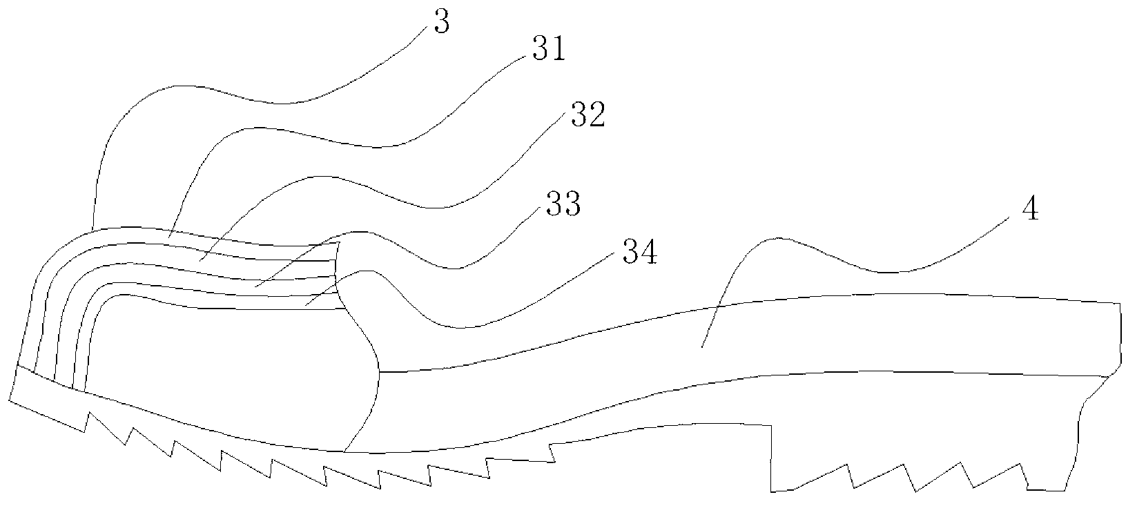
[0027] A reflective anti-piercing labor protection boot of this embodiment, such as Figure 2-7 As shown, it includes the sole, the toe, the upper and the shaft. The sole, the toe, the upper and the shaft all include a rubber outer layer and a lining layer. The lining layer is knitted cotton and the rubber outer layer of the boot The inner wall is glued with a steel cover, the steel cover is a grid steel cover composed of three vertical ribs and three transverse ribs, and the vertical ribs are arranged on the horizontal ribs, and the grid steel cover withstands impact force not less than 250J , The pressure resistance is not less than 17KN, so it can meet the requirements of most working conditions. Because the steel cover is in the form of a grid cover, on the one hand, it can save materials and reduce costs, on the other hand, it can reduce weight and be light to wear. The inner wall of the steel cover is bonded with a first elastic rubber layer, and the first elastic rubber l...
Embodiment 2
[0030] The difference between this embodiment and embodiment 1 lies in Figure 8-10 As shown, a light-emitting diode is provided in the middle of the toe, a power supply is provided at the base of the shoe sole, a switch is provided at the shaft of the boot or the foot root of the sole, and the light-emitting diode, power supply, and switch are connected in series, and the power supply is lithium battery.
Embodiment 3
[0032] The difference between this embodiment and the above embodiment lies in Figure 11-13 As shown, the power source is a spontaneous power source, the spontaneous power source includes a pressure power generation unit and a power storage unit, the pressure power generation unit and the power storage unit are arranged at the foot of the shoe sole, and the pressure power generation unit is connected to the power storage unit The input ends of the power storage unit, the light emitting diodes and the switch are connected in series, the pressure generating unit includes a pressure plate, a housing, a magnet, and one or more rectangular coils, and the rectangular coils are cylindrical Distributedly arranged, the magnets are arranged on the inner wall of the housing, the pressure plate is fixedly connected to one end of the rectangular coil through a spring, a rotating shaft is arranged in the middle of the inner bottom of the housing, and the other end of the rectangular coil is ...
PUM
 Abstract
Description
Claims
Application Information