
A capacitive electrode for detecting electrocardiographic signals of car drivers

An electrocardiographic signal and capacitive electrode technology, applied in the field of bioelectrical signal detection, can solve the problems of increasing the manufacturing cost of capacitive electrodes, reducing the anti-interference performance of capacitive electrodes, and being inactive, so as to provide electromagnetic shielding, suppress motion artifacts, low cost effect

Inactive Publication Date: 2016-03-30
CENT SOUTH UNIV
View PDF7 Cites 0 Cited by
  • Summary
  • Abstract
  • Description
  • Claims
  • Application Information

AI Technical Summary

Problems solved by technology

The first method greatly increases the production cost of the capacitor electrode; the second method makes the circuit structure of the capacitor electrode complicated, and too many electronic devices will introduce a lot of noise. If the design is unreasonable, it will reduce the impedance of the capacitor electrode. interference performance; the third method makes the mechanical structure of the capacitive electrode complicated, which greatly affects the application flexibility of the capacitive electrode
In addition, most of the existing capacitive electrode designs only include signal detection components without buffer components. When used for signal detection, the capacitive electrodes are fixed and cannot be moved, and slight movement of the measured object’s body will cause obvious motion artifacts. film

Method used


Image

  • A capacitive electrode for detecting electrocardiographic signals of car drivers
  • A capacitive electrode for detecting electrocardiographic signals of car drivers
  • A capacitive electrode for detecting electrocardiographic signals of car drivers

Examples


Embodiment Construction

[0019] The present invention will be further described below in conjunction with the accompanying drawings and embodiments.

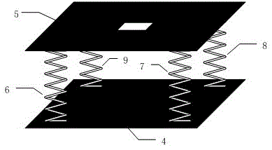
[0020] Such as figure 2 Shown is a structural diagram of an embodiment of the present invention, including a support component 4 , a signal detection component 5 and a buffer component. The buffer component is composed of a spring 6 , a spring 7 , a spring 8 and a spring 9 .

[0021] Support part 4 adopts aluminum plate, and its dimension is selected as 15 12cm, the thickness is selected as 0.2cm. The aluminum plate is used to provide support and at the same time provide electromagnetic shielding for the signal detection components.

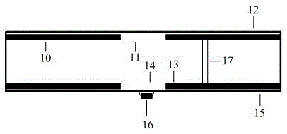
[0022] The signal detection part 5 is composed of a double-sided PCB board with a voltage buffer circuit, and its two-dimensional longitudinal section structure diagram is as follows: image 3 shown. The size selection of the PCB board used in this embodiment is 15 12cm, the thickness is selected as 0.3cm. Such as...


PUM


Abstract

The invention discloses a capacitor electrode for detecting electrocardiogram signals of a motorist. The capacitor electrode for detecting the electrocardiogram signals of the motorist comprises a supporting component, a signal detecting component and a buffer component, wherein the supporting component is composed of a metal plate; the signal detecting component is composed of a double-sided PCB (printed circuit board) with a voltage snubber circuit, the voltage snubber circuit is arranged on the bottom surface of the PCB and comprises CMOS (Complementary Metal-Oxide-Semiconductor Transistor) type double precision operational amplifiers with high input impedance and low noise; and the buffer component is composed of springs and is used for connecting the supporting component and the signal detecting component. The capacitor electrode for detecting the electrocardiogram signals of the motorist utilizes the double-sided PCB as the signal detecting component so that the structure is simple and the cost is low; utilizes springs as the buffer component so that the motion artifact caused by the body movement of a detected object during a signal detecting process is effectively restrained; and utilizes the mental plate as the supporting component so that not only a supporting function is achieved, but also an electromagnetic shielding function for the signal detecting component is achieved.

Description

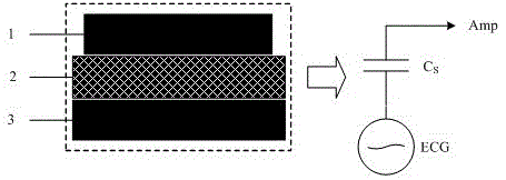
technical field [0001] The invention belongs to the technical field of bioelectric signal detection and relates to a capacitive electrode used for detecting electrocardiographic signals of automobile drivers. Background technique [0002] By monitoring the ECG signal of the car driver, the degree of fatigue can be detected, thereby preventing fatigue driving. Traditional ECG detection methods mostly use metal electrodes to directly contact the skin of the subject to obtain signals, but the particularity of the driving environment does not allow this traditional detection method. [0003] In recent years, non-contact ECG detection technology has begun to develop rapidly, so that ECG signals can be detected without touching the subject's skin. Non-contact ECG detection technology uses the principle of capacitive coupling to detect ECG signals in the form of displacement current. [0004] Such as figure 1 Shown is a schematic diagram of non-contact ECG detection. The capaci...

Claims


Application Information

Patent Timeline
Patent Type & Authority Patents(China)
IPC IPC(8): A61B5/0408
Inventor 徐效文贺金义赵于前
Owner CENT SOUTH UNIV
Learn More