
Welding device for welding pins on pin tube

A welding device and a welding pin technology are applied in the field of welding devices for welding pins on pin pipes, which can solve the problems of low work efficiency and high labor intensity, and achieve the effects of reducing labor intensity and improving work efficiency.

Inactive Publication Date: 2013-08-07
ZHANGJIAGANG HUADONG BOILER
View PDF8 Cites 6 Cited by
  • Summary
  • Abstract
  • Description
  • Claims
  • Application Information

AI Technical Summary

Problems solved by technology

At present, the workers hold the stud welding torch to weld the pins on the outer surface of the steel pipe in turn. This manual welding of the pins is not only labor-intensive, but also low in efficiency.

Method used


Image

  • Welding device for welding pins on pin tube
  • Welding device for welding pins on pin tube

Examples


Embodiment Construction

[0013] The present invention will be further described below in conjunction with the accompanying drawings and specific embodiments.

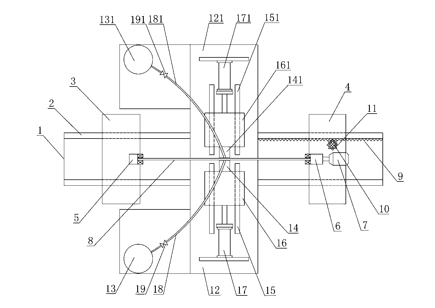
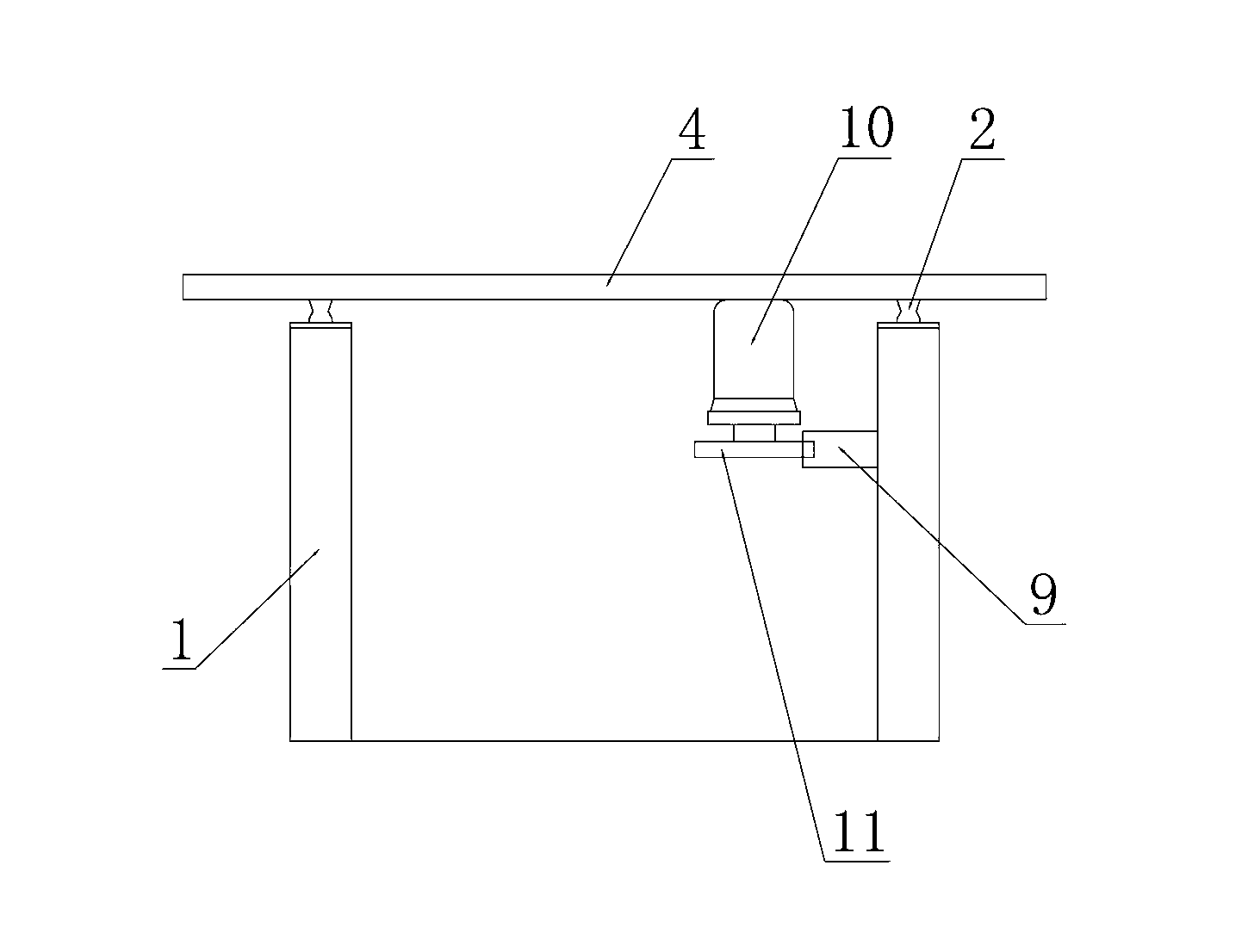
[0014] Such as figure 1 , figure 2 As shown, the described welding device for welding the pin on the pin tube includes: a main frame 1, a pair of rails 2 are arranged on the main frame 1 along its longitudinal direction, and the rails 2 are provided with a first The walking bracket 3 and the second walking bracket 4 are provided with an insulating steel pipe slewing support seat 5 that can movably support the steel pipe 8 on the first walking bracket 3, and an insulating steel pipe 8 that can clamp the steel pipe 8 is movably supported on the second walking bracket 4. The steel pipe clamp 6; the steel pipe clamp 6 rotates under the drive of the rotating motor 7 installed on the second traveling support 4, and drives the steel pipe 8 clamped between the steel pipe slewing bearing seat 5 and the steel pipe clamp 6 to rotate; the second travelin...


PUM


Abstract

The invention discloses a welding device for welding pins on a pin tube. The welding device comprises a main frame, wherein a rail is arranged on the main frame, a first walking support and a second walking support which can move along the rail are arranged on the rail, a steel tube slewing bearing seat capable of supporting a steel tube movably is arranged on the first walking support, and a steel tube clamp capable of clamping the steel tube is movably supported on the second walking support. The steel tube clamp rotates under driving of a rotating motor arranged on the second walking support and synchronously drives the steel tube clamped between the steel tube slewing bearing seat and the steel tube clamp to rotate. The second walking support moves along the rail under driving of a translation mechanism and drives the steel tube to longitudinally translate along the main frame. At least one pin welding mechanism capable of welding the pins on the surface of the steel tube is arranged on the main frame between the first walking support and the second walking support. The welding device can efficiently weld the pins on the steel tube sequentially and is high in work efficiency and low in worker labor intensity.

Description

technical field [0001] The invention relates to welding equipment applied to pin tubes of industrial boilers, in particular to a welding device for welding pins on the pin tubes. Background technique [0002] In industrial boilers, the water wall is the main heating part of the boiler. The pin tube water cooling wall is a commonly used water cooling wall, which is mainly welded by several pin tubes side by side. At present, the workers hold the stud welding torch to weld the pins on the outer surface of the steel pipe successively. This manual welding of the pins not only has high labor intensity, but also has low work efficiency. Contents of the invention [0003] The object of the present invention is to provide a welding device for welding pins on pin tubes which can greatly improve working efficiency. [0004] In order to achieve the above object, the present invention adopts the following technical scheme: the welding device for welding the pin on the pin tube inclu...

Claims


Application Information

Patent Timeline
Patent Type & Authority Applications(China)
IPC IPC(8): B23K9/20B23K9/12B23K9/28
Inventor 黄达其唐瑜
Owner ZHANGJIAGANG HUADONG BOILER
Features
  • Generate Ideas
  • Intellectual Property
  • Life Sciences
  • Materials
  • Tech Scout
  • Unparalleled Data Quality
  • Higher Quality Content
  • 60% Fewer Hallucinations
Learn More