
Display device, color film substrate and manufacturing method of color film substrate

A color filter substrate and a manufacturing method technology, applied in optics, instruments, nonlinear optics, etc., can solve problems such as uneven color pixel layers, affecting the flatness of the film surface in the color filter substrate, affecting product quality, etc.

Inactive Publication Date: 2013-08-07
BOE TECH GRP CO LTD +1
View PDF4 Cites 7 Cited by
  • Summary
  • Abstract
  • Description
  • Claims
  • Application Information

AI Technical Summary

Problems solved by technology

[0007] The technical problem to be solved by the present invention is to provide a display device, a color filter substrate and a manufacturing method thereof, so as to overcome the problem in the prior art that the two sides of the color pixel layer are overlapped on the black matrix, causing the upper surface of the color pixel layer to appear Unevenness, which affects the flatness of the film surface in the color filter substrate, and causes defects in the production line that adversely affect product quality

Method used


Image

  • Display device, color film substrate and manufacturing method of color film substrate
  • Display device, color film substrate and manufacturing method of color film substrate
  • Display device, color film substrate and manufacturing method of color film substrate

Examples


Embodiment 1

[0037] The specific implementation manners of the present invention will be further described in detail below in conjunction with the accompanying drawings and embodiments. The following examples are used to illustrate the present invention, but are not intended to limit the scope of the present invention.

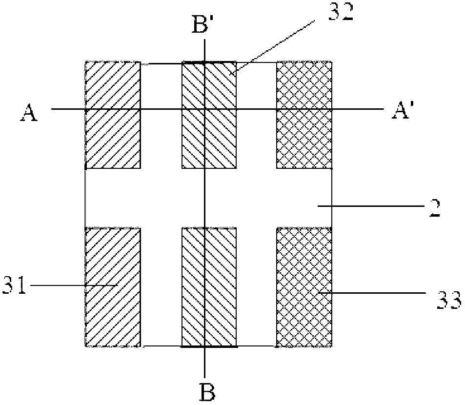
[0038] Such as figure 2 As shown, this embodiment takes TN (Twisted Nematic, twisted nematic) mode as an example, the color filter substrate includes: a substrate 1; a color pixel area, which includes a plurality of pixel units, and the pixel units include at least red sub-pixel units 31. The blue sub-pixel unit 33 and the green sub-pixel unit 32; the sub-pixel units of each color in the pixel unit are arranged at intervals on one side of the substrate 1; the black matrix 2 is arranged between the sub-pixel units of each color.

[0039] Wherein, the material of the substrate 1 can be transparent materials such as glass, quartz, resin, etc., which is not limited here. In...

Embodiment 2

[0049] Such as Figure 6 As shown, the embodiment of the present invention provides a method for manufacturing the above-mentioned color filter substrate, which includes:

[0050] Step S10, using a patterning process to form a color pixel area on the substrate, which includes a plurality of pixel units, and the pixel units at least include a red sub-pixel unit, a blue sub-pixel unit and a green sub-pixel unit; each color in the pixel unit The sub-pixel units are arranged on one side of the substrate at intervals.

[0051] In this step, sub-pixel units including a red sub-pixel unit 31 , a green sub-pixel unit 32 , and a blue sub-pixel unit 33 are formed on the substrate 1 by coating a color photoresist, exposing and developing. Since the sub-pixel units of each color are all fabricated on one side of the substrate 1, the flatness of the side surface is flatter than that of the sub-pixel units of each color arranged on the black matrix 2, and the “bull horn” phenomenon existin...


PUM


Abstract

The invention relates to the field of display technologies, in particular to a display deice, a color film substrate and a manufacturing method of the color film substrate. The color film substrate comprises a substrate, a color pixel region and black matrixes, wherein the color pixel region comprises a plurality of pixel units; every pixel unit at least comprises a red sub-pixel, a blue sub-pixel unit and a green sub-pixel unit; the various color sub-pixel units in every pixel unit are arranged on one side of the substrate at intervals; and the back matrixes are arranged among the various color sub-pixel units. According to the display deice, the color film substrate and the manufacturing method of the color film substrate, the color pixel region is firstly formed, and then an inkjet process is used to form the black matrixes, so that the angle step of the pixel units is reduced to the largest extent, the flatness of the surfaces of the pixel units is increased and the incidence rate of faulted production lines is effectively reduced; besides, the process of manufacturing the black matrixes through an inkjet mode is adopted, so that, on the one hand, the input costs of preliminary stage production lines are greatly reduced, and on the other hand, the material utilization amount for manufacturing the back matrixes can be reduced and the material utilization rate is improved, and therefore, the production costs are reduced.

Description

technical field [0001] The invention relates to the field of display technology, in particular to a display device, a color filter substrate and a manufacturing method thereof. Background technique [0002] In recent years, with the development of science and technology, liquid crystal display technology has also been continuously improved. TFT-LCD (Thin Film Transistor-Liquid Crystal Display, Thin Film Field Effect Transistor-Liquid Crystal Display) occupies an important position in the display field due to its advantages of good image display quality, low energy consumption, and environmental protection. At present, TFT-LCD is mainly formed by boxing an array substrate and a color filter substrate, and the cavity after the boxing is filled with liquid crystals. The existing color filter substrate is based on the color filter substrate of the three primary colors of red, green and blue. The liquid crystal panel controls the arrangement state of the liquid crystal molecules...

Claims


Application Information

Patent Timeline
IPC IPC(8): G02F1/1335G02F1/1333
CPCG02B5/201G02F1/133509G02F1/133516
Inventor 张思凯吴洪江王耸张继凯黎敏
Owner BOE TECH GRP CO LTD
Learn More