Cooling structure of high-speed permanent-magnet synchronous motor

A technology of permanent magnet synchronous motor and cooling structure, applied in the direction of magnetic circuit shape/style/structure, electric components, electrical components, etc., can solve the problems of increasing the overall design complexity of high-speed motors, and achieve the goal of reducing temperature, ensuring working temperature, weight reduction effect

Inactive Publication Date: 2013-08-07
XI AN JIAOTONG UNIV
View PDF4 Cites 9 Cited by
  • Summary
  • Abstract
  • Description
  • Claims
  • Application Information

AI Technical Summary

Problems solved by technology

[0003] The traditional solution is to add a blower to the outside to provide air intake, which increases the complexity of the overall design of the high-speed motor

Method used


Image

  • Cooling structure of high-speed permanent-magnet synchronous motor

Examples


Embodiment Construction

[0014] The present invention will be further described below in conjunction with the accompanying drawings and embodiments.

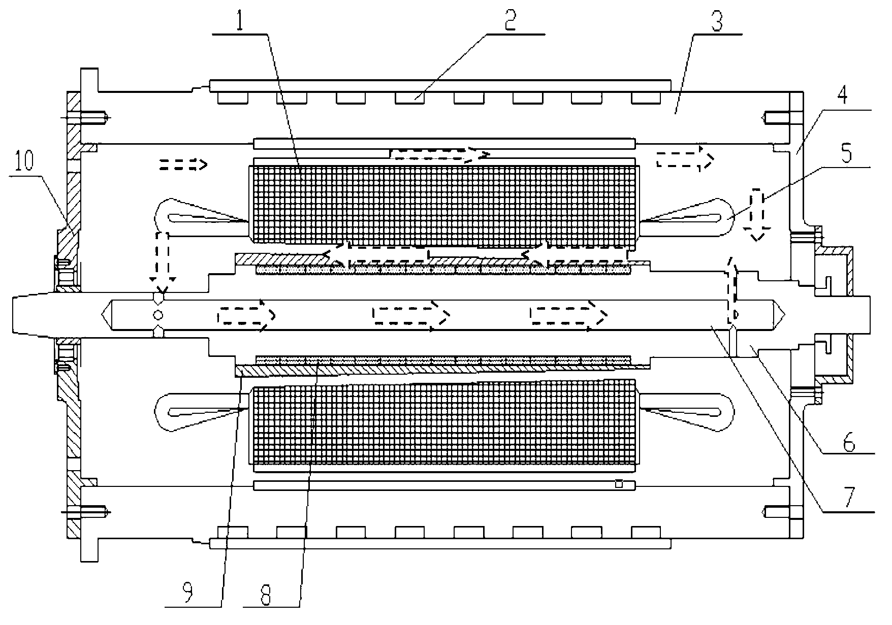
[0015] As shown in the figure, a cooling structure of a high-speed permanent magnet synchronous motor includes a motor rotor 6, the motor rotor 6 is installed inside the motor stator 1, and is supported on the motor front end cover 10 and the motor rear end cover 4, and the motor front end cover 10 is installed In the front section of the motor housing 3, a front end cavity is formed between the motor front end cover 10 and the motor stator 1, the motor rear end cover 4 is installed at the rear end of the motor housing 3, and a motor rear end cover 4 and the motor stator 1 are formed. The rear end cavity is provided with an air gap between the motor stator 1 and the motor housing 3. The motor rotor 6 adopts a hollow structure 7 to facilitate heat dissipation. The two ends of the motor rotor 6 are provided with ventilation holes, and the ventilation holes...


PUM


Abstract

Disclosed is a cooling structure of a high-speed permanent-magnet synchronous motor. An air gap runner between protective sheaths of the surfaces of a motor stator and a motor rotor is axially obliquely arranged. During operating of the motor, centrifugal force generated during high-speed rotation forces air in the air gap runner to flow and accelerate air circulation, vent holes are reserved on the surface of the rotor, and the air can further cool the inside of the rotor. Air circulation is facilitated by an air gap reserved between the motor stator and a motor housing, a water jacket is additionally arranged outside the motor housing, thus, the structure of additionally mounting a fan on a motor shaft in conventional design is omitted, and vibration and noise are reduced. The cooling structure can form two channels of air cooling circulation and one channel of water cooling circulation, and cooling effect is greatly improved.

Description

technical field [0001] The invention belongs to the technical field of high-speed permanent magnet synchronous motors, and in particular relates to a cooling structure for high-speed permanent magnet synchronous motors. Background technique: [0002] At present, the cooling method widely used in high-speed permanent magnet synchronous motors is to ventilate and cool the stator of the motor or liquid circulation forced cooling, and rarely involves the cooling of the rotor. When most motors are ventilated and cooled, an axial flow fan is installed on the rotor for forced cooling. Medium circulation, but when the motor is running at high speed, the overall strength and vibration of the motor need to be recalculated. [0003] The traditional solution is to add a blower to the outside to provide air intake, which increases the complexity of the overall design of the high-speed motor. Contents of the invention [0004] In order to overcome the above-mentioned shortcomings of th...

Claims


Application Information

Patent Timeline
Patent Type & Authority Applications(China)
IPC IPC(8): H02K1/32H02K5/20
Inventor 孙岩桦高南沙虞烈段福伟李智
Owner XI AN JIAOTONG UNIV
Why Eureka
Try Eureka