Worm member for rotary working table

A technology of rotary table and worm rod, which is applied in the direction of metal processing machinery parts, manufacturing tools, metal processing equipment, etc. It can solve the problems of limited bearing capacity, affecting the accuracy of the whole machine, and the inability to guarantee the accuracy of the axial runout of the rotary table. To achieve the effect of firm fixation and convenient clutch adjustment

Inactive Publication Date: 2013-08-14
GAOYOU LIBO MACHINE TOOL ACCESSORIES FACTORY
View PDF0 Cites 0 Cited by
  • Summary
  • Abstract
  • Description
  • Claims
  • Application Information

AI Technical Summary

Problems solved by technology

[0002] The existing rotary table includes the following forms: 1. The rotary table is lifted by hydraulic pressure and then falls down after rotation, and the structural form of the rotary table is positioned by the Hirth plate. Although the positioning accuracy is high, the rotary table cannot participate in the linkage. The workbench and the workpiece need to be lifted during processing, and this structural form can only be used in small-sized rotary worktables; 2. The load-bearing capacity of the rotary worktable supported by rolling blocks is significantly enhanced, but the inlays in contact with the roller blocks The processing and splicing of the steel surface is highly technical and difficult, and because the rolling block is originally used for linear motion, but when doing circular motion, the rolling block rollers are in a state of rolling and sliding superimposition, so this type of rotary work The table is not suitable for high-speed rotation, and its bearing capacity is limited; 3. The large-scale rotary table supported by static pressure has a large load-bearing capacity and can be used for high-speed rotation. In the pressure structure, the processing and manufacturing requirements of the static pressure surface are high, the production process is complicated, the production cycle is long, and the hydraulic system is prone to fluctuations. Machine precision
[0003] In addition, the following problems still exist in the rotary table that cooperates with the worm and the turbine: the adjustment of the clutch between the worm and the turbine is troublesome, and only professionals can adjust it; there is easy gap between the worm and the worm sleeve; The worm sleeve is not fixed firmly, etc.

Method used


Image

  • Worm member for rotary working table

Examples


Embodiment Construction

[0014] The present invention will be further described below through specific embodiments. It should be pointed out that for those of ordinary skill in the art, without departing from the principle of the present invention, some modifications and improvements can also be made, and these should also be regarded as belonging to the present invention. protection scope of the invention.

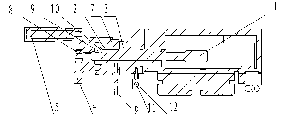
[0015] The rotary table drives the turbine of the turbine assembly to rotate through the worm of the worm assembly, thereby driving the rotation of the working table. Worm member of the present invention such as figure 1 As shown, the worm member includes a worm 1, a worm sleeve 2, a worm sleeve fixing seat 3, a hand wheel 4, a handle 5, a clutch disc puller 6 and a clutch disc 7; the worm 1 is provided with a worm sleeve 2 The worm cover 2 is fixed on the worm cover holder 3; the hand wheel 4 is fixed on the worm 1; the hand wheel 4 is connected with the handle 5; superior. The hand wheel 4 i...


PUM


Abstract

The invention discloses a worm member used for a rotary working table. The worm member comprises a worm, a worm sleeve, a worm sleeve fixing seat, a hand wheel, a handle, a separation and reunion disc poking rod and a separation and reunion disc. The worm sleeve is arranged outside the worm and fixed in the worm sleeve fixing seat. The hand wheel is fixed on the worm, the handle is connected onto the hand wheel, the separation and reunion disc poking rod is arranged on the separation and reunion disc used for controlling the worm. The separation and reunion adjustment of the worm and a worm wheel is convenient. The worm member can prevent the effect on an axial gap of the worm and the worm sleeve caused by displacement of a worm locking nut and the worm sleeve due to friction between the worm locking nut and the worm sleeve in rotating of the worm. A worm sleeve locking rod has the effect of locking the worm sleeve and enables the worm and the worm sleeve to be firmly fixed.

Description

technical field [0001] The invention relates to a component, in particular to a worm component for a rotary table. Background technique [0002] The existing rotary table includes the following forms: 1. The rotary table is lifted by hydraulic pressure and then falls down after rotation, and the structural form of the rotary table is positioned by the Hirth plate. Although the positioning accuracy is high, the rotary table cannot participate in the linkage. The workbench and the workpiece need to be lifted during processing, and this structural form can only be used in small-sized rotary worktables; 2. The load-bearing capacity of the rotary worktable supported by rolling blocks is significantly enhanced, but the inlays in contact with the roller blocks The processing and splicing of the steel surface is highly technical and difficult, and because the rolling block is originally used for linear motion, but when doing circular motion, the rolling block rollers are in a state ...

Claims


Application Information

Patent Timeline
IPC IPC(8): B23Q1/26
Inventor 吴小青吴廷飞
Owner GAOYOU LIBO MACHINE TOOL ACCESSORIES FACTORY
Why Eureka
Try Eureka