Single-tube spiral flow stabilizer

A spiral and steady flow technology, applied in the field of single-tube spiral flow stabilizer, can solve the problems of low feeding or unloading efficiency, unstable operation, simple structure, etc., and achieve the effect of compact structure, stable operation and meeting production requirements

Inactive Publication Date: 2013-08-14
JIANGSU HEAVEN BOW FACILITY ENG
View PDF3 Cites 2 Cited by
  • Summary
  • Abstract
  • Description
  • Claims
  • Application Information

AI Technical Summary

Problems solved by technology

However, the existing technology of the spiral stabilizer has simple structure, unstable operation, high noise, low feeding or unloading efficiency, and cannot meet the production requirements.

Method used


Image

  • Single-tube spiral flow stabilizer

Examples


Embodiment Construction

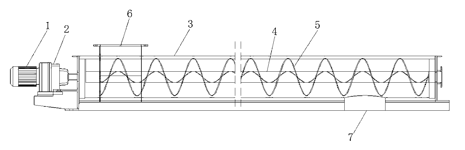
[0009] The present invention will be described in further detail below in conjunction with the accompanying drawings.

[0010] Such as figure 1 As shown, the single-tube spiral flow stabilizer includes a motor 1, a reducer 2 connected to the motor 1, a delivery pipe 3, a screw shaft 4 arranged in the delivery tube 3, and a screw shaft 4 connected to the screw shaft 4. The screw blade 5, the screw shaft 4 is connected with the rotating shaft of the reducer 2, the front end of the delivery pipe 3 is provided with a material inlet 6, and the rear end of the delivery pipe 3 is provided with a material discharge 7, the rotation of the screw shaft 4 drives the rotation of the screw blade 5 so that the material is conveyed from the material inlet 6 to the material outlet 7; Stable, in addition, the helical blade 5 has the function of evenly stirring the material and facilitating feeding.

[0011] The material feeding port 6 is square. In this embodiment, the square port is not easy...


PUM


Abstract

The invention relates to the technical field of spiral flow stabilizers, in particular to a single-tube spiral flow stabilizer. The stabilizer comprises a motor, a speed reducer, a delivery pipe, a spiral shaft and a spiral blade. The speed reducer is connected with the motor, the spiral shaft is arranged in the delivery pipe, the spiral blade is connected with the spiral shaft, the spiral shaft is connected with a rotary shaft of the speed reducer, a material inlet is arranged at the front end of the delivery pipe, a material outlet is arranged at the rear end of the delivery pipe, and the spiral shaft rotates to drive the spiral blade to rotate to deliver materials from the material inlet to the material outlet. According to the single-tube spiral flow stabilizer, the spiral shaft is driven by the motor to rotate to drive the spiral blade to rotate, so that the materials are delivered from the material inlet to the material outlet. The flow stabilizer has the advantages of being stable in operation, low in noise, compact in structure and capable of adjusting the material flow and meeting actual production requirements.

Description

technical field [0001] The invention relates to the technical field of a spiral flow stabilizer, in particular to a single-pipe spiral flow stabilizer. Background technique [0002] At present, the spiral stabilizer is mainly suitable for continuous and uniform feeding of dry powdery materials, such as feeding and short-distance transportation of powdery materials such as raw meal, coal powder, cement, etc., and is often used for unloading at the bottom of powder storage . However, the spiral flow stabilizer in the prior art has simple structure, unstable operation, high noise, low feeding or unloading efficiency, and cannot meet the requirements of production. Contents of the invention [0003] The object of the present invention is to provide a single-pipe spiral flow stabilizer with simple structure, balanced operation, low noise, high feeding or unloading efficiency and meeting production requirements. [0004] In order to solve the existing problems of the backgroun...

Claims


Application Information

Patent Timeline
Patent Type & Authority Applications(China)
IPC IPC(8): B65G33/14B65G33/24
Inventor 邵苏平
Owner JIANGSU HEAVEN BOW FACILITY ENG
Why Eureka
Try Eureka