A Hydraulic Cylinder Control Valve Without Unloading Shock Resonance

A technology of hydraulic cylinders and control valves, which is applied in mining equipment, earthwork drilling, pillars/brackets, etc., and can solve problems such as weld cracking, cylinder overload expansion, and hydraulic control stop valve spring force that cannot be adjusted according to needs.

Active Publication Date: 2015-07-29
BEIJING TIANMA INTELLIGENT CONTROL TECH CO LTD
View PDF7 Cites 0 Cited by
  • Summary
  • Abstract
  • Description
  • Claims
  • Application Information

AI Technical Summary

Problems solved by technology

Moreover, the phenomenon that the one-way valve core of the hydraulic control check valve is pushed away from the valve seat of the hydraulic control check valve and then closed continues for many times, forming resonance, and the maximum amplitude can be 2 to 3 times that before unloading, resulting in a Components connected by one-way valve sealing, such as safety valve overload damage, weld cracking, cylinder overload expansion, etc.
Although the first inventor of this patent application invented the method of using rod seals to suppress the impact and resonance amplitude 30 years ago, at present, this method is still used for column control all over the world, but the suppression effect is different under different conditions. Satisfied, in some places the amplitude of shock and resonance is still relatively large, even causing damage to the safety valve
[0003] In the prior art, there is a hydraulic control shut-off valve, such as figure 2 As shown, the sealing diameter (2F) of the spool (202) of the hydraulically controlled globe valve and the valve seat (203) of the hydraulically controlled globe valve and the diameter (2G) of the valve core sealing section of the hydraulically controlled globe valve and the diameter of the hydraulically controlled globe valve The diameter (2H) of the spool return section of the stop valve is the same. Applying its principle to the hydraulic cylinder control of the coal mine hydraulic support can achieve the purpose of no unloading shock resonance, but its structure is complex, and its hydraulic control stop valve The screw sleeve (204) of the hydraulic control shut-off valve installed on the left side of the valve body (201) is threadedly connected with the spring sleeve (209) of the spring (206) of the hydraulic control shut-off valve, and the spring force of the hydraulic control shut-off valve cannot be adjusted as required. Adjustment, the spool (202) of the hydraulic control shut-off valve is threadedly connected with the spring seat (205) of the hydraulic control shut-off valve, and there is a plug (207) on the right side of the valve body (201) of the hydraulic control shut-off valve. The seat (205) of the valve has a seat support (208), there are many places that need to be sealed, especially the control diameter is the diameter (2H) of the liquid return section of the valve core of the hydraulic control stop valve, which can only be used When the small channel system is used for the control of the large channel and large diameter system of the coal mine hydraulic support such as a column, the valve core (202) of the hydraulic control shut-off valve and the valve port sealing diameter of the existing hydraulic control shut-off valve (203) ( 2F), the diameter of the spool sealing section (2G) of the hydraulically controlled globe valve and the diameter of the spool return section (2H) of the hydraulically controlled globe valve need to be increased by the same value, which will inevitably cause a significant decrease in the control pressure and easily cause miscontrol. There are security risks

Method used


Image

  • A Hydraulic Cylinder Control Valve Without Unloading Shock Resonance
  • A Hydraulic Cylinder Control Valve Without Unloading Shock Resonance
  • A Hydraulic Cylinder Control Valve Without Unloading Shock Resonance

Examples


specific Embodiment approach 1

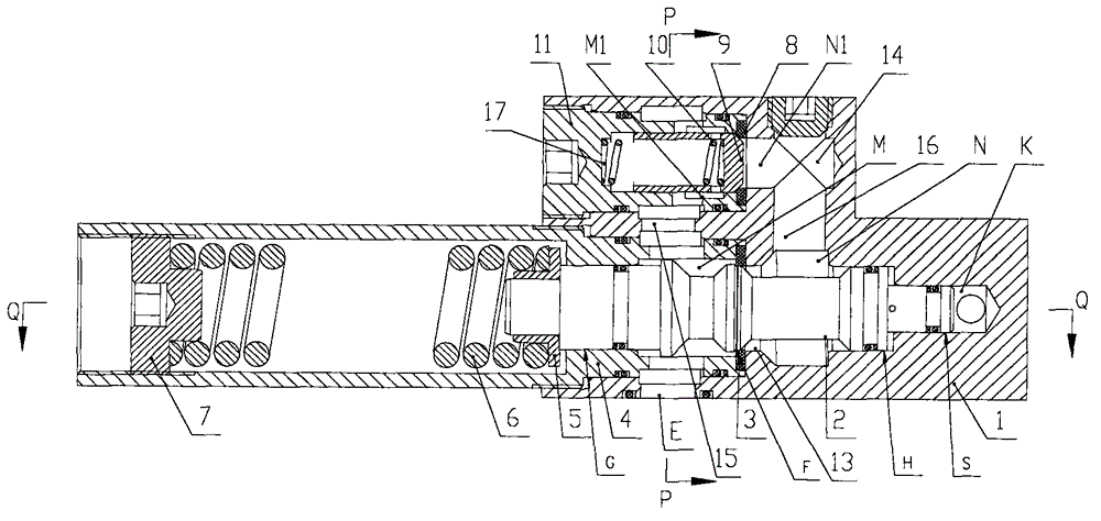
[0058] Such as Figure 3 ~ Figure 5 As shown, the technical solution adopted in the present invention includes a valve body 1, in which a valve body main hole 13, a valve body auxiliary hole 14, a first communication hole 15 and a second communication hole 16 are processed, and in the valve body Install the first valve seat 3, the first valve core 2, the sleeve 4 and the sealing member in the main hole 13, and install the spring seat 5, the first spring 6 and the pressure regulating screw in the sleeve 4. 7. Install the first spool 2, the sleeve 4 and the seal in the main hole 13 of the valve body to form the main hole sealing chamber M, the main hole liquid return chamber N and the control chamber K. The first spool 2 includes In addition to the diameter G of the sealing section of the same diameter as the sealing diameter F of the valve port and the diameter H of the liquid return section, there is also a diameter S of the control section with a smaller diameter. The diamet...

specific Embodiment approach 2

[0060] Such as Figure 6 As shown, the technical solution adopted in Embodiment 2 of the present invention is the same as that in Embodiment 1, the difference is that the valve body 1 is connected with a plate-type connection check valve 601 that communicates with it in place of the auxiliary hole check valve 601 in the valve body 1. The one-way valve 17 has a plate-type connection check valve sealing cavity 6M2 and a plate-type connection check valve liquid inlet chamber 6N2 in the valve body of the plate-type connection check valve 601, and the main hole seal chamber M and the plate-type connection check valve seal cavity 6M2 It communicates with the plate connection, and leads to the plate connection interface E, and communicates with the fifth interface C and the sixth interface C1. The main hole liquid return chamber N communicates with the plate connection check valve inlet chamber 6N2 during the plate connection. , and communicate with the first interface A and the seco...

specific Embodiment approach 3

[0061] Such as Figure 7 As shown, the technical solution adopted in Embodiment 3 of the present invention is the same as that in Embodiment 1, the difference is that the pipe connection check valve 701 connected to the valve body 1 outside the valve body 1 replaces the auxiliary valve 701 in the valve body 1. The hole check valve 17, in the valve body of the pipe type connection check valve 701, has a pipe type connection check valve sealing chamber 7M2 and a pipe type connection check valve inlet chamber 7N2, the main hole sealing chamber M and the pipe type Connect the check valve sealing chamber 7M2 to communicate with the pipe connection, and communicate with the plate connection interface E, the fifth interface C and the sixth interface C1, the first interface A, the second interface A1, the main hole liquid return chamber N It communicates with the liquid inlet cavity 7N2 of the pipe connection check valve 701 by installing a tee 702 and a section of communication pipe ...


PUM


Abstract

The invention discloses a hydraulic cylinder control valve without unloading impact resonance, which overcomes the problem that impact resonance is generated by the unloading of a hydraulic control one-way valve of a conventional hydraulic cylinder. The hydraulic cylinder control valve without unloading impact resonance is characterized in that: a sealing diameter of a valve opening of a first valve core inside a valve body is same as a diameter of a sealing section and a diameter of a liquid return section; and the diameter of a control section is smaller than the diameter of a liquid return section. The beneficial effects are that: as the sealing diameter of the valve opening of a first valve core is same as the diameter of the sealing section and the diameter of the liquid return section, the unloading impact resonance problem of the control valve of the hydraulic cylinder is solved; as the sealing diameter of the valve opening, the diameter of the sealing section and the diameter of the liquid return section can be increased equivalently, and the diameter of the control section can be reduced at will based on a need, the control pressure is unlikely too low, and no false operation is generated; and a secondary-hole one-way valve arranged in a secondary hole inside the valve body or a plate-shaped connecting one-way valve or a tubular one-way valve outside the valve body are used for raising a column, so that needs of big channel for dropping the column, a small channel for raising the column, and joint control of a balancing jack and a lifting jack while the column is raised are satisfied.

Description

technical field [0001] The invention belongs to the technical field of hydraulic control, in particular to a hydraulic cylinder control valve without unloading impact resonance for coal mine hydraulic supports. Background technique [0002] Such as figure 1 As shown, in the prior art, the column, the front beam and the tail beam hydraulic cylinder of the coal mine hydraulic support are all controlled by the hydraulic control check valve 100, and hydraulic shock resonance will be generated when the hydraulic control check valve is unloaded. Taking the column as an example, When lifting the column, the high-pressure liquid opens the check valve core 103 of the hydraulic control check valve, leaves the valve seat 102 of the hydraulic control check valve and enters the lower chamber of the column, forcing the live column to rise, and the upper end of the live column is lifted to contact with the top beam of the hydraulic support and Firmly support the roof and keep a roof on th...

Claims


Application Information

Patent Timeline
Patent Type & Authority Patents(China)
IPC IPC(8): E21D15/51E21D23/16
Inventor 李继周张文全
Owner BEIJING TIANMA INTELLIGENT CONTROL TECH CO LTD
Why Eureka
Try Eureka