
avionics bay with lrm

A technology for avionics and aircraft, applied in electrical equipment casings/cabinets/drawers, mechanical equipment, electrical components, etc. Reduce vibration and enhance heat dissipation

Active Publication Date: 2022-01-18
四川省安道速博科技有限公司
View PDF16 Cites 0 Cited by
  • Summary
  • Abstract
  • Description
  • Claims
  • Application Information

AI Technical Summary

Problems solved by technology

[0005] In the electronic devices of avionics equipment, the degree of circuit integration of semiconductor devices is getting higher and higher. The increase in the degree of circuit integration of semiconductor devices and the limitation of shortening their running time require that the volume size of electronic devices or devices be reduced as much as possible, but in this way will lead to an increase in heat flux
The increase in heat flux will increase the temperature of avionics equipment, and the temperature of semiconductor components will increase by 10 ℃, and the reliability will decrease by 50%
Moreover, the normal operation of electronic components requires a uniform distribution of temperature. Uneven temperature distribution will generate thermal stress and thermal denaturation inside the electronic device, which will easily cause fatigue damage, even mechanical fracture and permanent deformation of the electronic device in the long run, affecting the The performance of electronic devices and even the entire system

Method used


Image

  • avionics bay with lrm
  • avionics bay with lrm
  • avionics bay with lrm

Examples


Embodiment

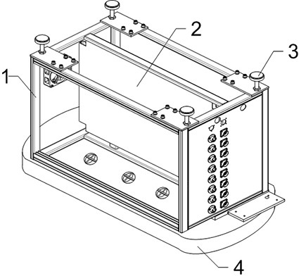
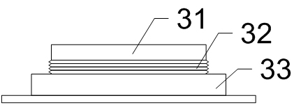
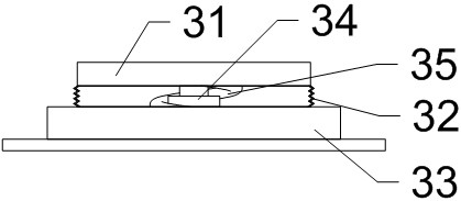
[0037] like Figure 1~8 As shown, the avionics cabin equipped with LRM includes a cabin body 1, a vertically fixed avionics equipment fixing plate 2 is arranged in the cabin body 1, and several top fixing feet 3 are fixed above the cabin body 1 , the top fixing feet 3 are used for: fixedly connecting the cabin body 1 and the aircraft body, and buffering the cabin body 1 from the vibration of the aircraft body; a vibration-reducing and heat-dissipating air cushion 4 is fixed below the cabin body 1 , the upper surface of the described vibration damping and cooling air cushion 4 is provided with several exhaust ports 44, and pressure relief valves are arranged in the described exhaust ports 44. The gas injection pipe 41 for the cooling air cushion 4 injects gas, and the exhaust port 44 faces the avionics fixing plate 2 .

[0038] In this embodiment, the position of the cabin body 1 is fixed through the joint action of the top fixed feet 3 and the vibration-damping and heat-dissi...


PUM


Abstract

The invention discloses an avionics cabin equipped with an LRM, which includes a cabin body, a vertically fixed avionics equipment fixing plate is arranged in the cabin body, and several top fixing legs are fixed above the cabin body. The top fixing feet are used for: fixedly connecting the cabin body with the aircraft body, and buffering the cabin body from the vibration of the aircraft body; below the cabin body, a vibration-reducing and heat-dissipating air cushion is fixed, and the vibration-damping and heat-dissipating air cushion Several exhaust ports are opened on the upper surface, and pressure relief valves are arranged in the exhaust ports, and an air injection pipe is fixed below the vibration-reducing and heat-dissipating air cushion. The invention realizes the functions of fixing, shock absorption and enhancing heat dissipation at the same time by using the same placement compartment, so that the space in the aircraft is saved, and at the same time, the damage to the avionics equipment caused by vibration and temperature changes can be avoided.

Description

technical field [0001] The invention relates to the field of maintenance of avionics equipment, in particular to an avionics cabin equipped with an LRM. Background technique [0002] The performance of modern avionics equipment plays an increasingly important role in aircraft performance. When evaluating aircraft performance, the level of various electronic equipment equipped on the aircraft is an important reference index. [0003] Avionics equipment is mainly installed in the electronic equipment compartment in the belly of the aircraft, and a small part is installed in the nose and tail of the aircraft. The electronic equipment is fixed on the placement bin through the front and rear locking mechanisms, and the placement bin is installed on the corresponding position of the aircraft through four shock absorbers. [0004] During the use of avionics equipment, the airport will be affected by the vibration and impact of the aircraft engine itself, the external start-up dist...

Claims


Application Information

Patent Timeline
Patent Type & Authority Patents(China)
IPC IPC(8): H05K5/02H05K7/20F16F15/023F16F15/04F16F15/06B64D47/00
CPCH05K5/0234H05K5/0217H05K5/0204H05K7/20009F16F15/0232F16F15/046F16F15/06B64D47/00F16F2222/126
Inventor 杨小丽
Owner 四川省安道速博科技有限公司
Learn More