Emission control system for internal combustion engine

An emission control system, a technology for an internal combustion engine, applied in the directions of engine control, fuel injection control, electrical control, etc., can solve problems such as deterioration of exhaust gas

Inactive Publication Date: 2013-08-14
DENSO CORP
View PDF7 Cites 1 Cited by
  • Summary
  • Abstract
  • Description
  • Claims
  • Application Information

AI Technical Summary

Problems solved by technology

As a result, exhaus

Method used


Image

  • Emission control system for internal combustion engine
  • Emission control system for internal combustion engine
  • Emission control system for internal combustion engine

Examples


no. 1 example )

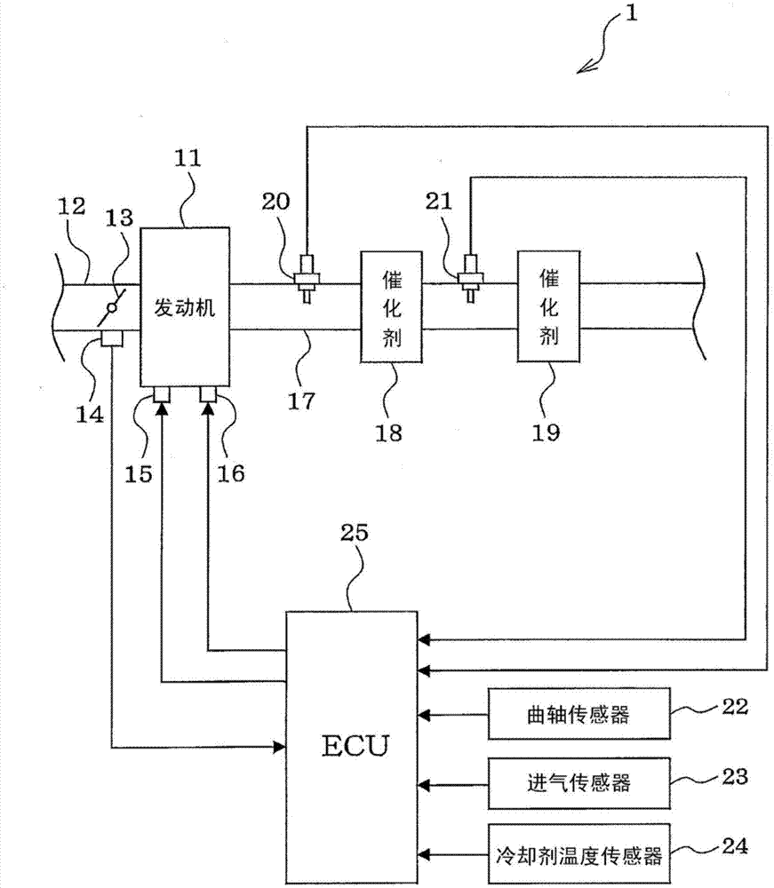
[0029] will refer to Figure 1 to Figure 9 A first embodiment of the present disclosure will be described. First, based on figure 1 The emission control system 1 of the present embodiment is described.

[0030] The emission control system 1 includes an engine 11 (internal combustion engine), an intake pipe 12 through which intake air flows and is drawn into the engine 11 , a throttle valve 13 provided in the intake pipe 12 , and a throttle sensor 14 provided in the intake pipe 12 . The throttle sensor 14 detects the throttle opening of the throttle valve 13 by adjusting the opening (throttle opening) of the throttle valve 13 using a motor or the like. The engine 11 includes fuel injection valves 15 respectively attached to cylinders of the engine 11 to inject fuel into the cylinders or into intake portions of the cylinders, and spark plugs 16 respectively disposed adjacent to the cylinders of the engine 11. cylinder head. Spark plug 16 creates an electrical spark to ignite...

no. 2 example )

[0074] will refer to Figure 10 The second embodiment will be described. Explanation of parts in the second embodiment that are substantially the same as those in the first embodiment will be omitted or simplified, and parts in the second embodiment that are different from the first embodiment will be mainly described.

[0075] In the first embodiment, when the execution condition of the rich direction control (rich direction condition) is satisfied during the fueling stop control, the rich RSP control is started. In the second embodiment, ECU25 (or microcomputer 26) executes Figure 10 The routine for emission reduction control is shown, and rich RSP control is started early after rich directional control is started.

[0076] exist Figure 10 In the routine of the emission reduction control shown in , it is first determined in step 201 whether or not the refueling stop control is executed. When it is determined in step 201 that the fueling stop control is to be executed, ...

no. 3 example )

[0082] will refer to Figures 11 to 13 A third embodiment will be described. Explanation of parts in the third embodiment that are substantially the same as those in the first embodiment will be omitted or simplified, and in the third embodiment, parts that are different from the first embodiment will be mainly explained.

[0083] In the first embodiment, the rich direction control is terminated when the output of the oxygen sensor 21 exceeds the predetermined rich threshold value after the start of the rich direction control. In the third embodiment, the ECU 25 (or microcomputer 26) of the emission control system 1 executes Figure 13 The routine of the emission reduction control shown in , and when the estimated amount of oxygen stored in the upstream catalyst 18 (estimated stored oxygen amount) becomes equal to a predetermined reference threshold (ref.threshold), the rich direction control is terminated.

[0084] Specifically, as Figure 11 As shown, the fueling stop con...


PUM


Abstract

An emission control system for an engine includes a catalyst and an exhaust-gas sensor provided downstream of the catalyst in a flow direction of exhaust gas. The exhaust-gas sensor includes a sensor element that includes a pair of electrodes and a solid electrolyte body located between the electrodes. The emission control system further includes a constant current supply portion that changes an output characteristic of the exhaust-gas sensor by applying a constant current between the electrodes, a rich direction control portion that performs a rich direction control after a fuelling-stop control, and a characteristic control portion that performs a rich responsiveness control during the rich direction control. In the rich direction control, an air-fuel ratio of the exhaust gas is made to be richer. In the rich responsiveness control, the constant current supply portion increases a detection responsiveness of the exhaust-gas sensor with respect to rich gas.

Description

technical field [0001] The present disclosure relates to an emission control system of an internal combustion engine including a catalyst for purifying exhaust gas and an exhaust gas sensor disposed downstream of the catalyst in a flow direction of the exhaust gas. Background technique [0002] Generally, in order to increase the catalytic conversion efficiency of a catalyst for purifying exhaust gas, an emission control system of an internal combustion engine includes exhaust gas sensors (for example, air / fuel sensor and Oxygen Sensor). The exhaust gas sensor detects an air-fuel ratio of the exhaust gas, or detects whether the exhaust gas is rich or lean. [0003] When the air-fuel ratio of the exhaust gas changes from rich to lean or from lean to rich, changes in the output of an exhaust gas sensor such as an oxygen sensor may lag behind changes in the actual air-fuel ratio of the exhaust gas. Thus, the exhaust gas sensor can have room for improvement in detection respon...

Claims


Application Information

Patent Timeline
IPC IPC(8): F02D41/02
CPCF02D41/1456F02D41/22F02D41/1439F02D41/1455F01N11/00F02D41/02F02D41/1475F01N3/18
Inventor 中野孝亮中田真吾松冈干泰
Owner DENSO CORP
Why Eureka
Try Eureka